- 快召唤伙伴们来围观吧
- 微博 QQ QQ空间 贴吧
- 文档嵌入链接
- 复制
- 微信扫一扫分享
- 已成功复制到剪贴板
MOS场效应晶体管
展开查看详情
1 .J. Chen MOS Field-Effect Transistors (MOSFETs) Chapter 4
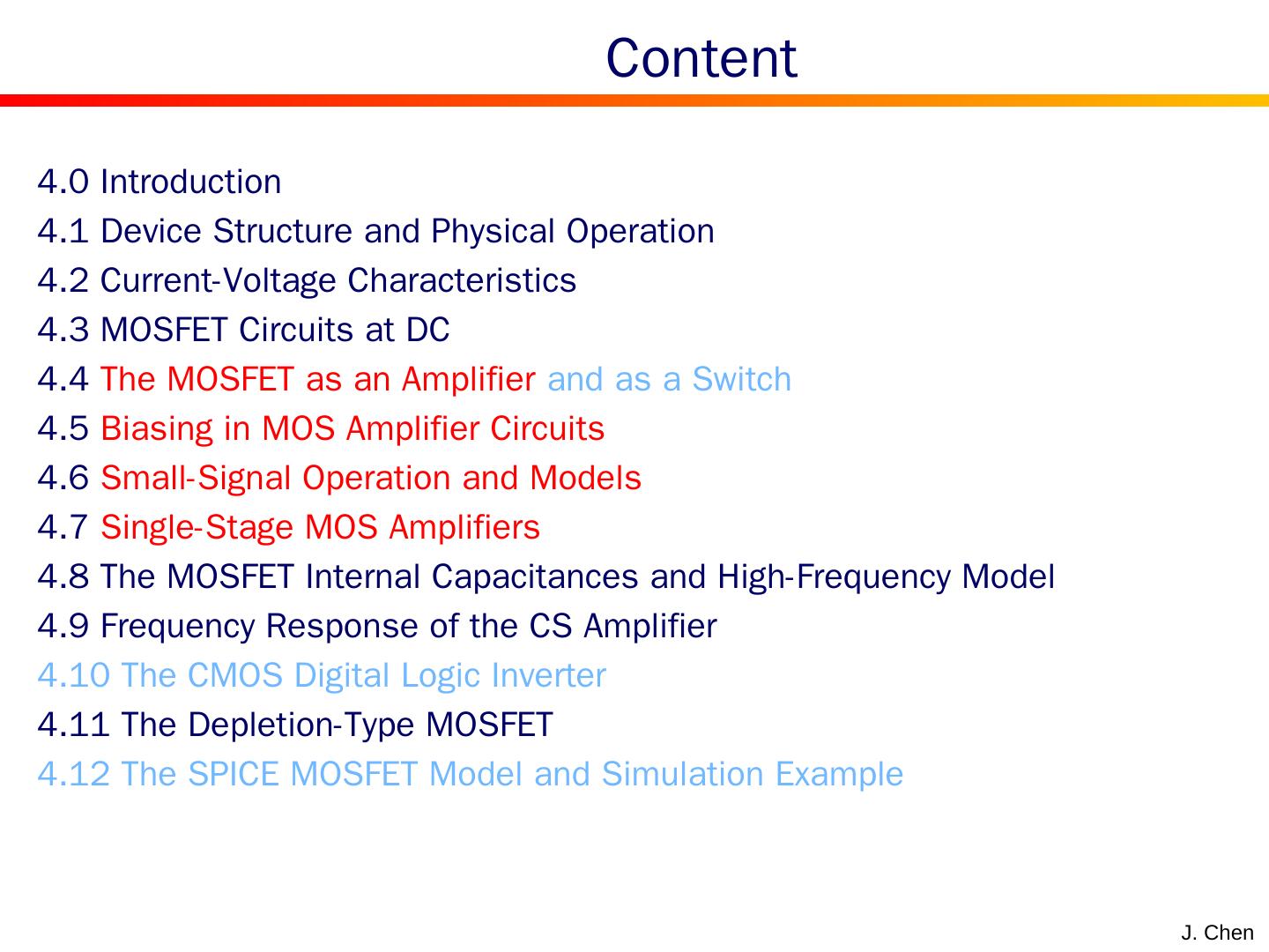
2 . Content J. Chen 4.0 Introduction 4.1 Device Structure and Physical Operation 4.2 Current-Voltage Characteristics 4.3 MOSFET Circuits at DC 4.4 The MOSFET as an Amplifier and as a Switch 4.5 Biasing in MOS Amplifier Circuits 4.6 Small-Signal Operation and Models 4.7 Single-Stage MOS Amplifi e rs 4.8 The MOSFET Internal Capacitances and High- Frequency Model 4.9 Frequency Response of the CS Amplifier 4.10 The CMOS Digital Logic Inverter 4.11 The Depletion-Type MOSFET 4.12 The SPICE MOSFET Model and Simulation Example
3 .4.0 Introduction to FET Three-terminal devices are far more useful than two-terminal ones, because they can be used in a multitude of applications, signal amplification digital logic memory circuits. …… The basic principle the use of the voltage between two terminals to control the current flowing in the third terminal . Transistor = trans fer re sistor J.P. Chen
4 .J. Chen FET: Field Effect Transistor There are two types MOSFET: metal-oxide-semiconductor FET JFET: Junction FET MOSFET is also called the insulated-gate FET or IGFET. Quite small Simple manufacturing process Low power consumption Widely used in VLSI circuits ( >billion on a single IC chip) 4.0 Introduction to FET
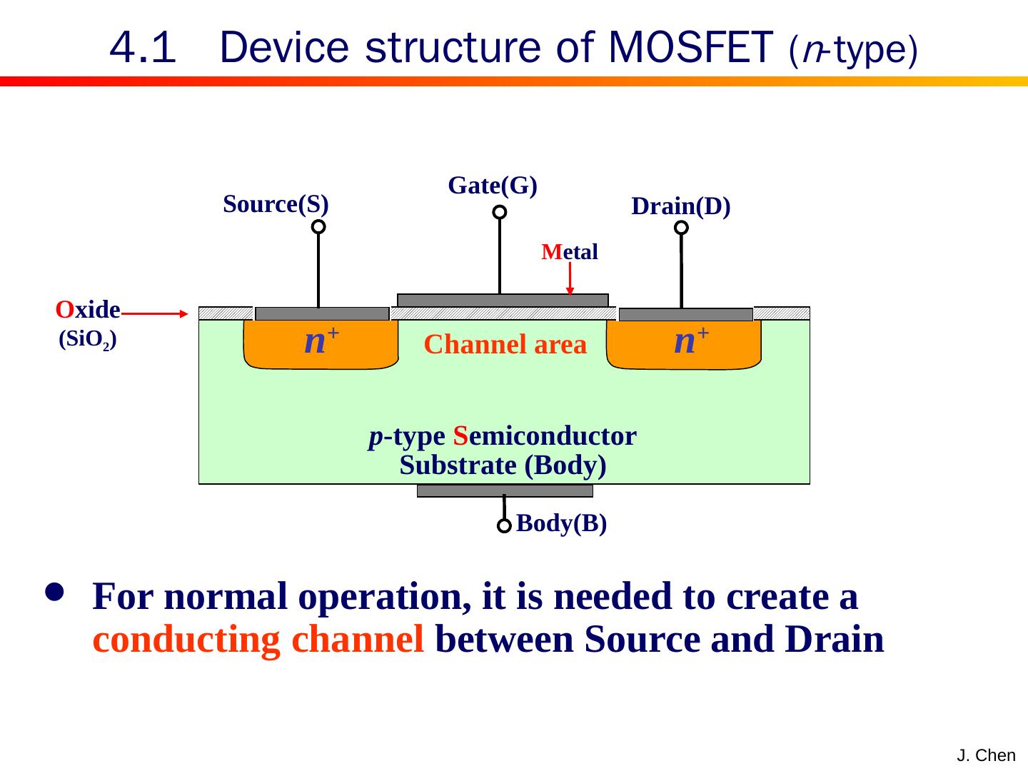
5 .J. Chen 4.1 Device structure of MOSFET ( n -type) p -type S emiconductor Substrate (Body) Body(B) n + n + O xide (SiO 2 ) Source(S) Gate(G) Drain(D) M etal For normal operation, it is needed to create a conducting channel between Source and Drain Channel area
6 .4.1 Creating a channel for current flow J. Chen An n channel can be induced at the top of the substrate beneath the gate by appl y i ng a positive voltage to the gate The channel is an inversion layer The value of V GS at which a sufficient number of mobile electrons accumulate to form a conducting channel is c alled the threshold voltage ( V t )
7 .J. Chen channel length L channel width oxide thickness T ox ( 2 to 50 nm) 4.1 Device structure of MOSFET Cross-section view feature size 特征尺寸 Main device dimensions
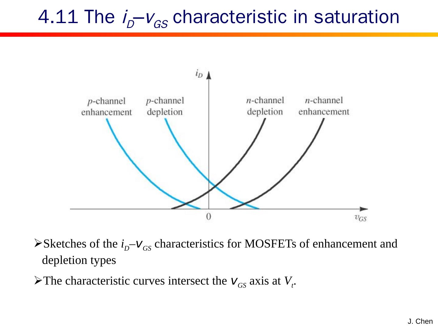
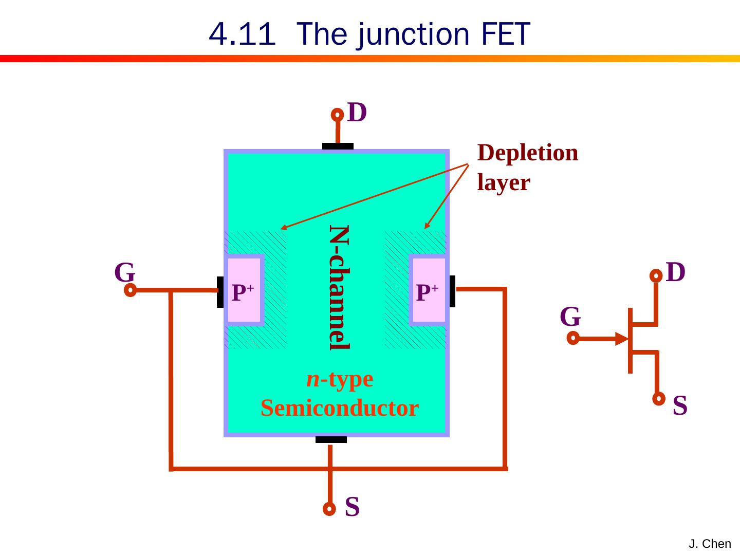
8 .J. Chen According to the type of the channel , FETs can be classified as MOSFET N channel P channel JFET P channel N channel 4.1 Classification of FET Enhancement type Depletion type Enhancement type Depletion type
9 .4.1 Drain current @ small voltage v DS J. Chen An NMOS transistor with v GS > V t and with a small v DS applied. The channel depth is uniform and t he device acts as a resistance. The channel conductance is proportional to effective voltage , or excess gate voltage, ( v GS – V t ) . Drain current is proportional to ( v GS – V t ) and v DS .
10 .4.1 Drain current @ small voltage v DS J. Chen
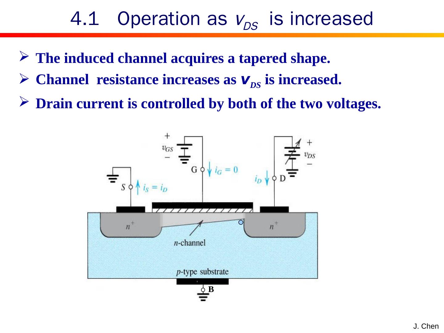
11 .J. Chen The induced channel acquires a tapered shape. Channel resistance increases as v DS is increased. Drain current is controlled by both of the two voltages. 4.1 Operation as v DS is increased B
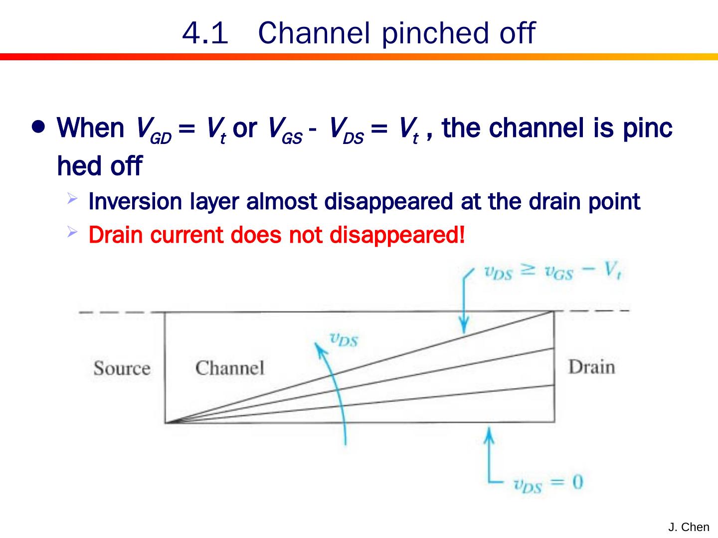
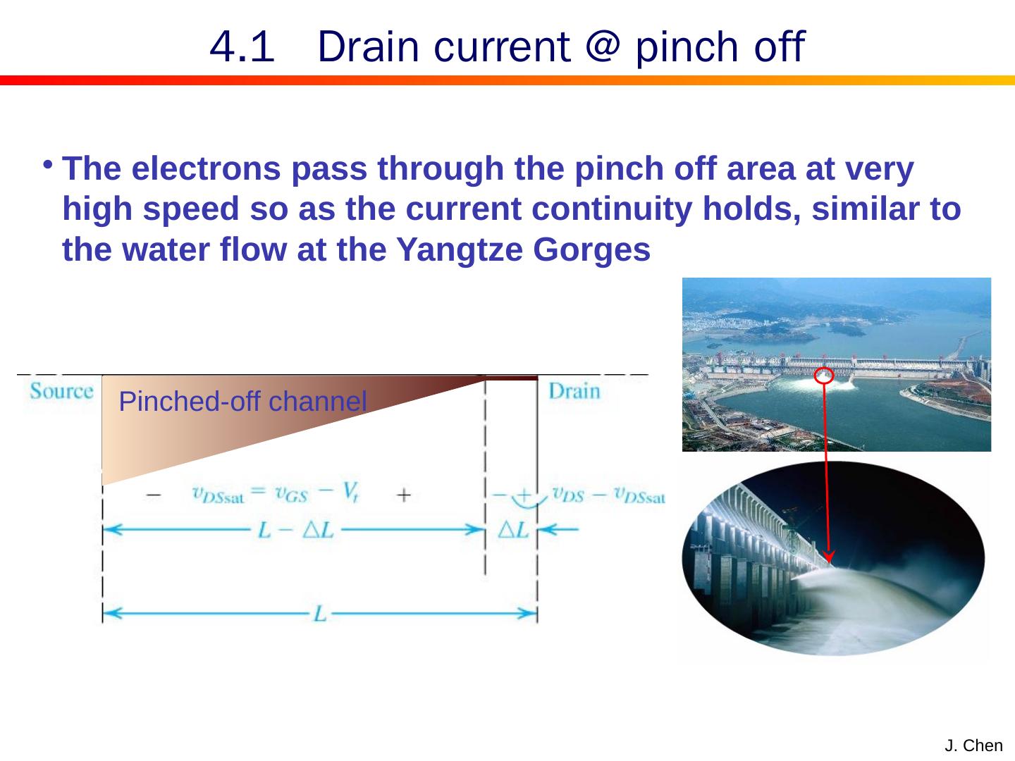
12 .J. Chen When V GD = V t or V GS - V DS = V t , the channel is pinched off Inversion layer almost disappeared at the drain point Drain current does not disappeared! 4.1 Channel pinched off
13 .J. Chen 4.1 Drain current @ pinch off The electrons pass through the pinch off area at very high speed so as the current continuity holds, similar to the water flow at the Yangtze Gorges Pinched-off channel
14 .J. Chen Drain current is saturated and only controlled by the v GS 4.1 Drain current @ pinch off
15 .J. Chen v GS creates the channel. Increasing v GS will increase the conductance of the channel. At saturation region only the v GS controls the drain current. At subthreshold region, drain current has the exponential relationship with v GS 4.1 Drain current controlled by v GS
16 .J. Chen Two reasons for readers to be familiar with p channel device 4.1 p channel device Existence in discrete-circuit. More important is the utilization of complementary MOS or CMOS circuits.
17 .J. Chen Structure of p channel device The substrate is n type and the inversion layer is p type. Carrier is hole. Threshold voltage is negative. All the voltages and currents are opposite to the ones of n channel device. Physical operation is similar to that of n channel device. 4.1 p channel device
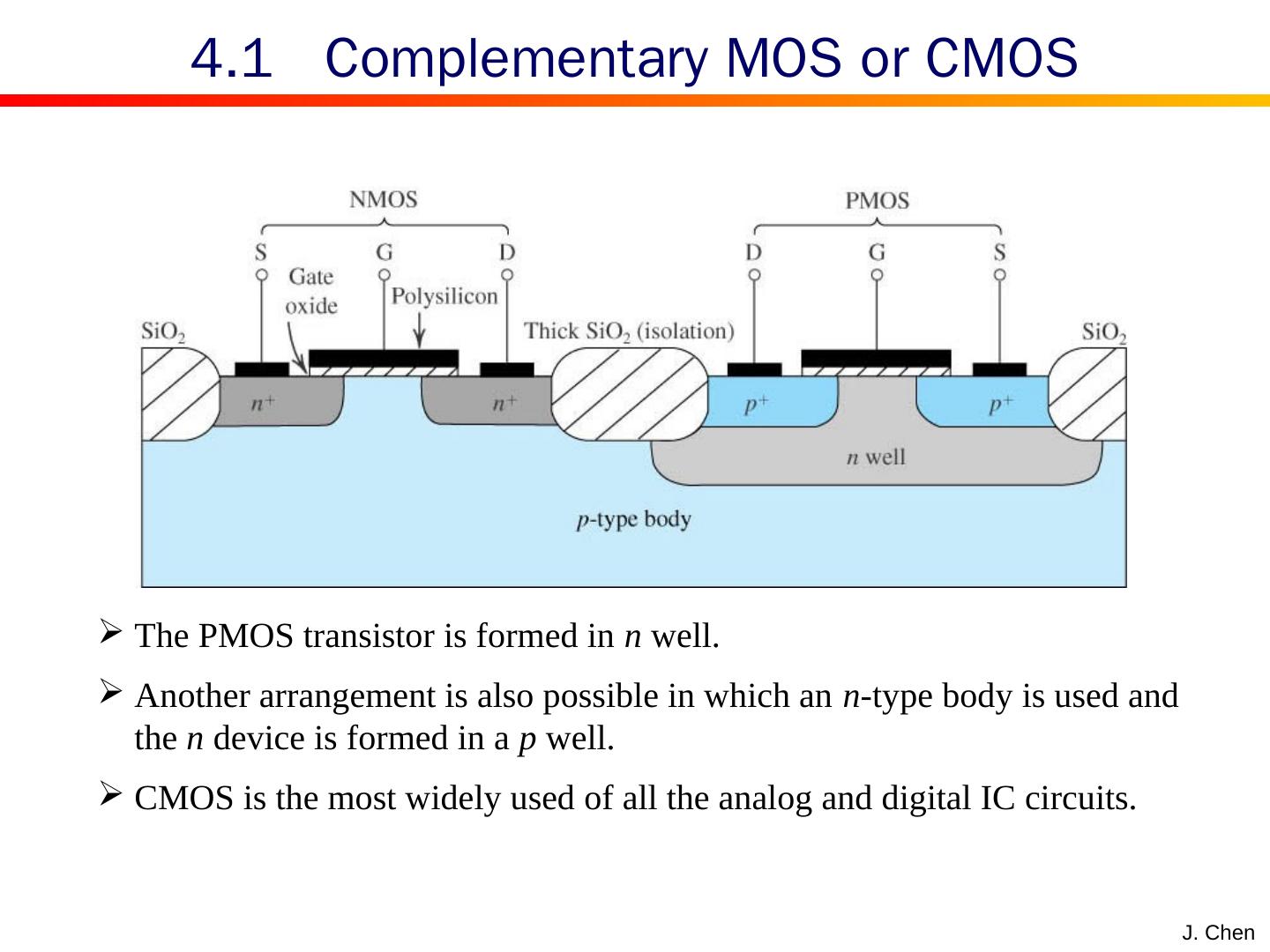
18 .J. Chen The PMOS transistor is formed in n well. Another arrangement is also possible in which an n -type body is used and the n device is formed in a p well. CMOS is the most widely used of all the analog and digital IC circuits. 4.1 Complementary MOS or CMOS
19 .J. Chen Circuit symbol Output characteristic curves Channel length modulation Characteristics of p channel device Body effect Temperature effects and Breakdown Region 4.2 Current-voltage characteristics
20 .J. Chen Circuit symbol for the n -channel enhancement-type MOSFET. Modified circuit symbol with an arrowhead on the source terminal to distinguish it from the drain and to indicate device polarity (i.e., n channel). (c) Simplified circuit symbol to be used when the source is connected to the body or when the effect of the body on device operation is unimportant. 4.2 Circuit symbol
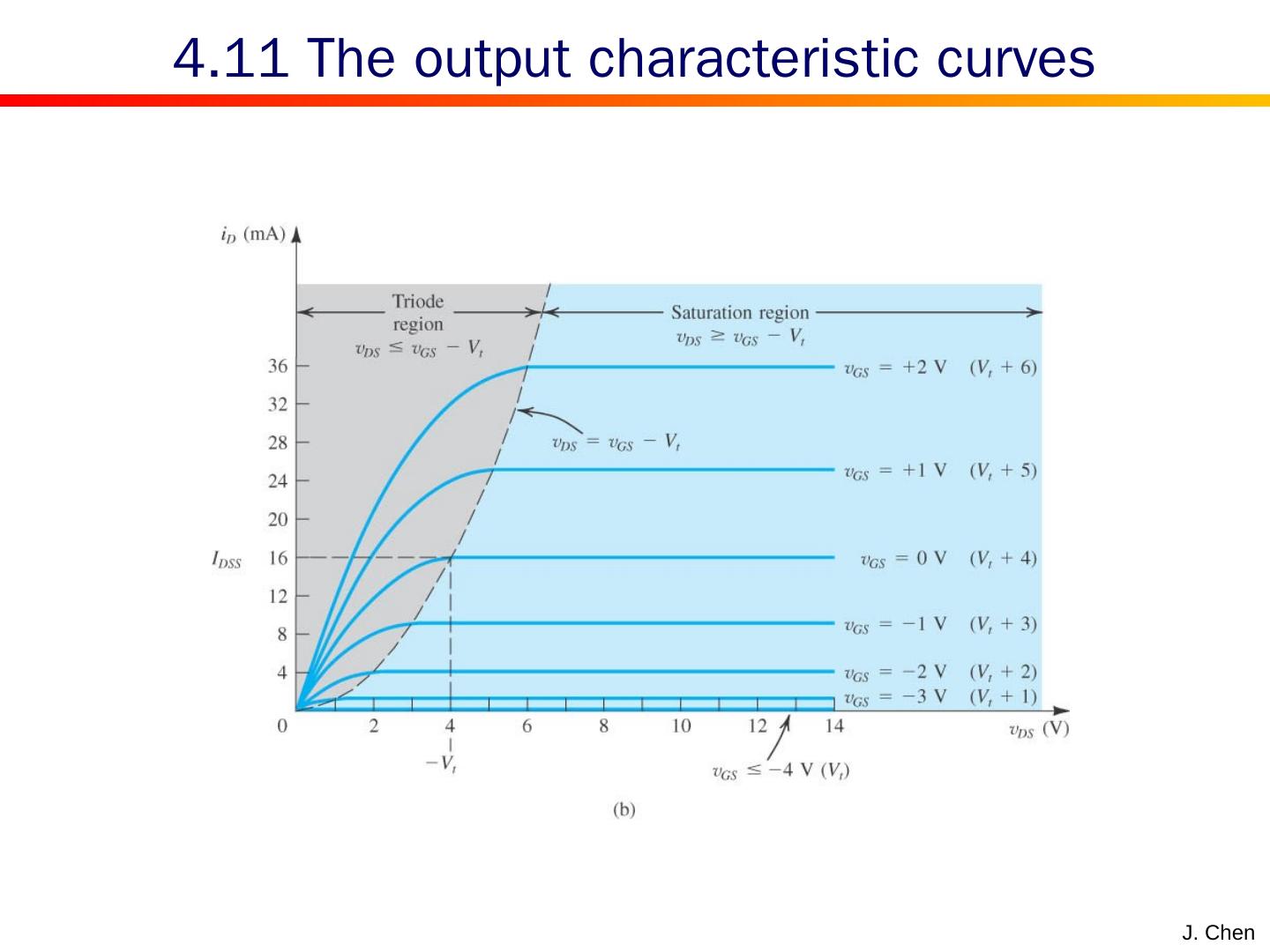
21 .J. Chen An n -channel enhancement-type MOSFET with v GS and v DS applied and with the normal directions of current flow indicated. The i D – v DS characteristics for a NMOS device Three distinct region Cutoff region Triode region Saturation region 4.2 Output characteristic curves
22 .J. Chen Biased voltage The transistor is turned off. Operating in cutoff region as a switch. 4.2 Cutoff r egion
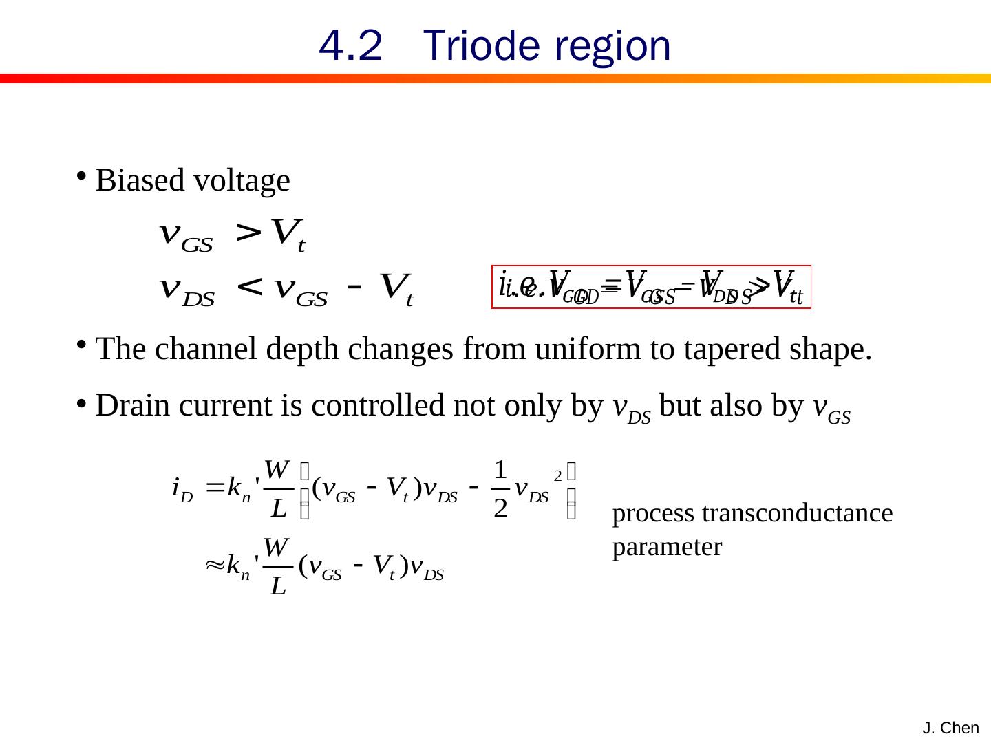
23 .J. Chen Biased voltage The channel depth changes from uniform to tapered shape. Drain current is controlled not only by v DS but also by v GS 4.2 Triode r egion process transconductance parameter
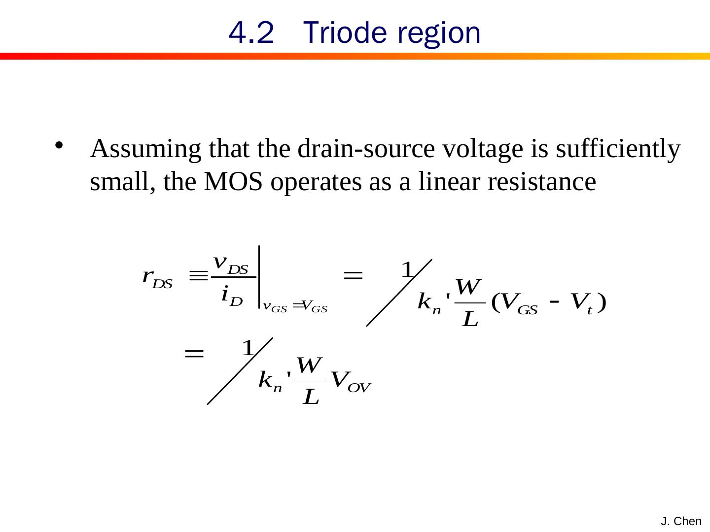
24 .J. Chen Assuming that the drain-source voltage is sufficiently small , t he MOS operates as a linear resistance 4.2 Triode r egion
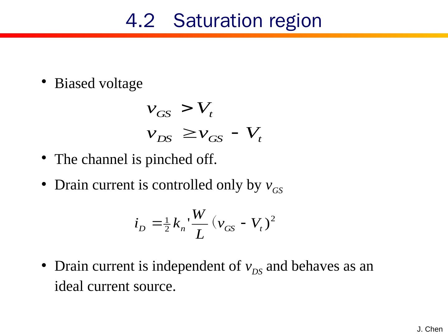
25 .J. Chen Biased voltage The channel is pinched off. Drain current is controlled only by v GS Drain current is independent of v DS and behaves as an ideal current source. 4.2 Saturation r egion
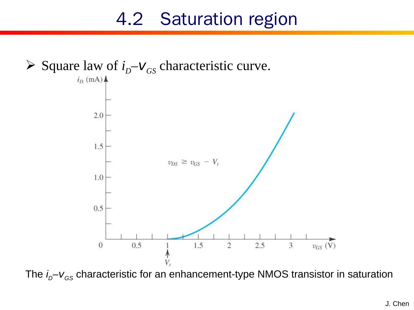
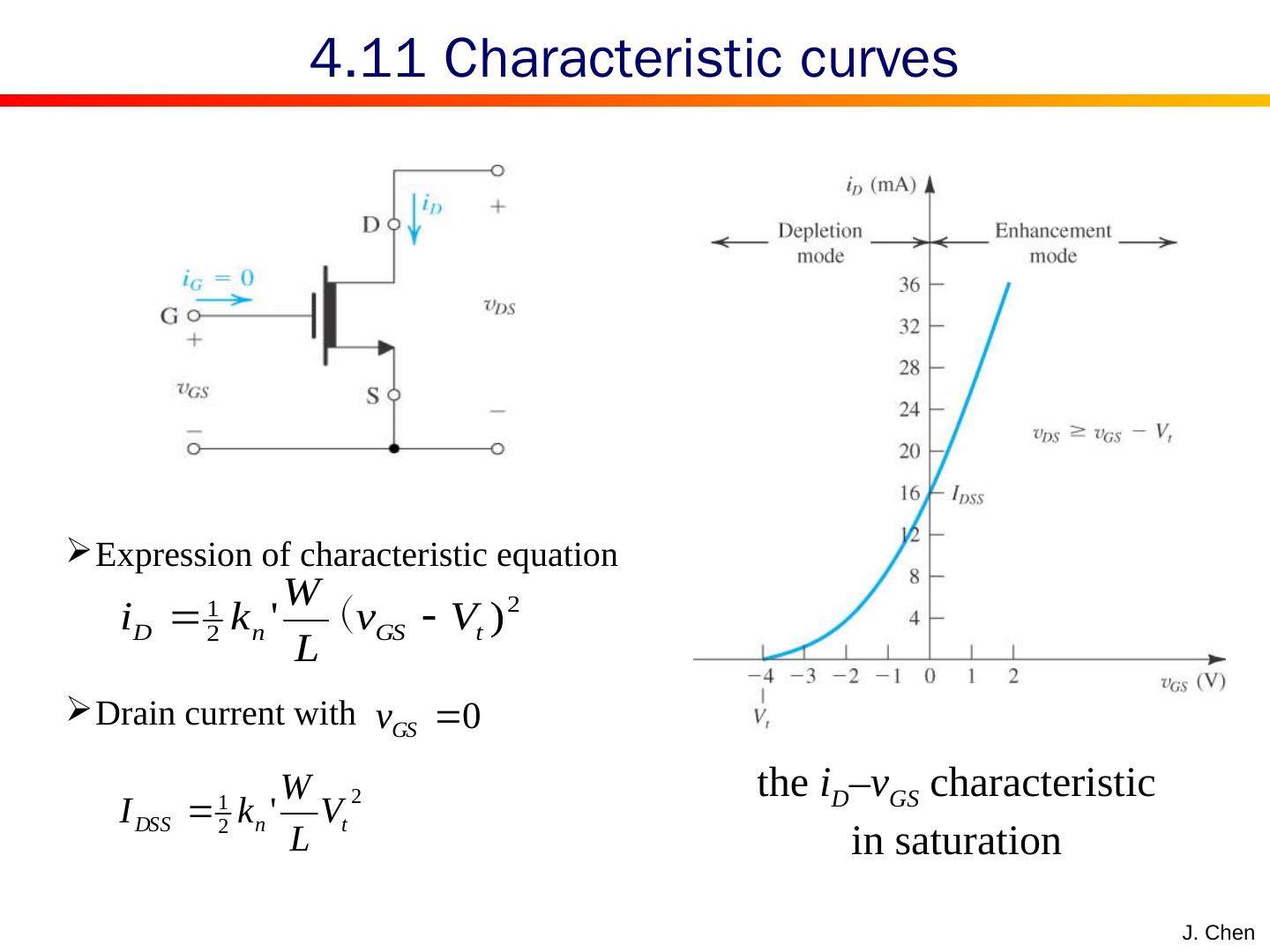
26 .J. Chen Square law of i D – v GS characteristic curve. 4.2 Saturation r egion The i D – v GS characteristic for an enhancement-type NMOS transistor in saturation
27 .J. Chen Pinched point moves to source terminal with the voltage v DS increased. Hence the effective channel length is reduced and channel resistance decreased Drain current increases with the voltage v DS increased . Current drain is modified by the channel length modulation 4.2 Channel l ength m odulation V A —— Early voltage , depending on the process technology and proportional to the channel length L .
28 .J. Chen MOS transistors don’t behave an ideal current source due to channel length modulation . The output resistance is finite. The output resistance is inversely proportional to the drain current. 4.2 Channel l ength m odulation
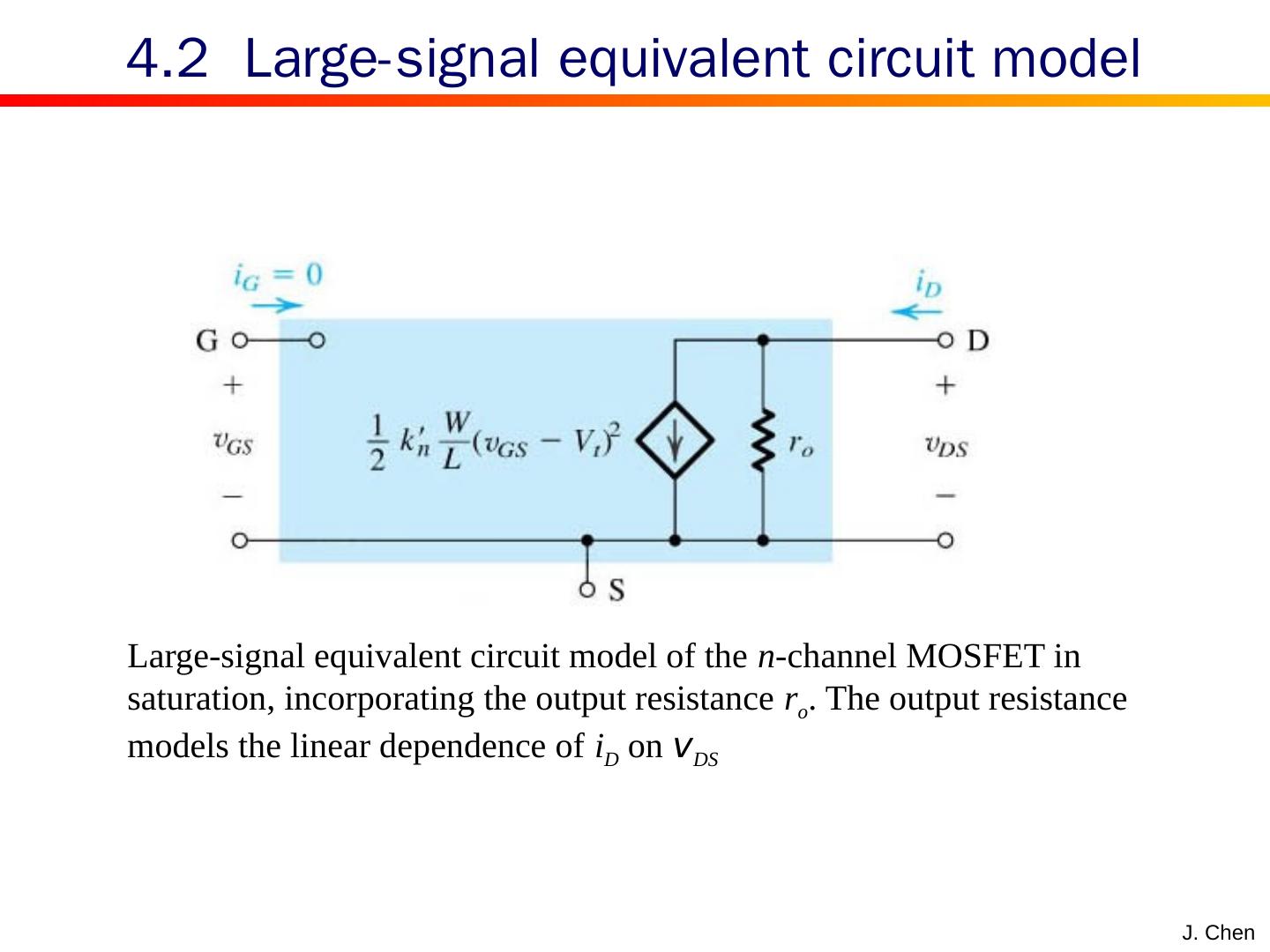
29 .J. Chen Large-signal equivalent circuit model of the n -channel MOSFET in saturation, incorporating the output resistance r o . The output resistance models the linear dependence of i D on v DS 4.2 Large- s ignal e quivalent c ircuit m odel


