- 快召唤伙伴们来围观吧
- 微博 QQ QQ空间 贴吧
- 文档嵌入链接
- 复制
- 微信扫一扫分享
- 已成功复制到剪贴板
流水线处理器的设计
展开查看详情
1 . ECE4680 Computer Organization and Architecture Designing a Pipeline Processor ECE4680 Pipeline.1 2002-4-3 A Single Cycle Processor Branch <31:26> RegDst Instruction<31:0> op Main ALUSrc Jump Control : <16:20> <21:25> <11:15> Instruction <0:15> Zero Fetch Unit Clk ALUop 3 Rd Rt Rd <5:0> ALU RegDst Imm16 1 Mux 0 func Control Rs Rt RegWr 5 5 5 ALUctr 3 busA MemWr MemtoReg Rw Ra Rb Zero busW 32 ALU 32 32-bit 32 0 Registers busB 0 32 Mux Clk Mux 32 32 WrEn Adr 1 Extender 1 Data In 32 imm16 Data 32 Instr<15:0> 16 Memory Clk ALUSrc ExtOp ECE4680 Pipeline.2 2002-4-3
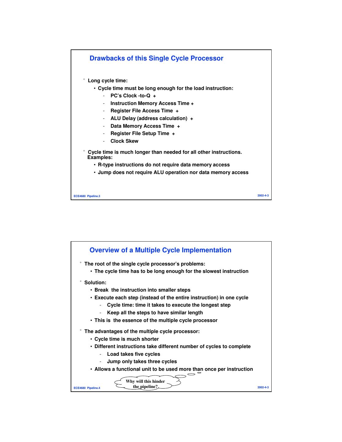
2 . Drawbacks of this Single Cycle Processor °Long cycle time: • Cycle time must be long enough for the load instruction: - PC’s Clock -to-Q + - Instruction Memory Access Time + - Register File Access Time + - ALU Delay (address calculation) + - Data Memory Access Time + - Register File Setup Time + - Clock Skew °Cycle time is much longer than needed for all other instructions. Examples: • R-type instructions do not require data memory access • Jump does not require ALU operation nor data memory access ECE4680 Pipeline.3 2002-4-3 Overview of a Multiple Cycle Implementation °The root of the single cycle processor’s problems: • The cycle time has to be long enough for the slowest instruction °Solution: • Break the instruction into smaller steps • Execute each step (instead of the entire instruction) in one cycle - Cycle time: time it takes to execute the longest step - Keep all the steps to have similar length • This is the essence of the multiple cycle processor °The advantages of the multiple cycle processor: • Cycle time is much shorter • Different instructions take different number of cycles to complete - Load takes five cycles - Jump only takes three cycles • Allows a functional unit to be used more than once per instruction Why will this hinder ECE4680 Pipeline.4 the pipeline? 2002-4-3
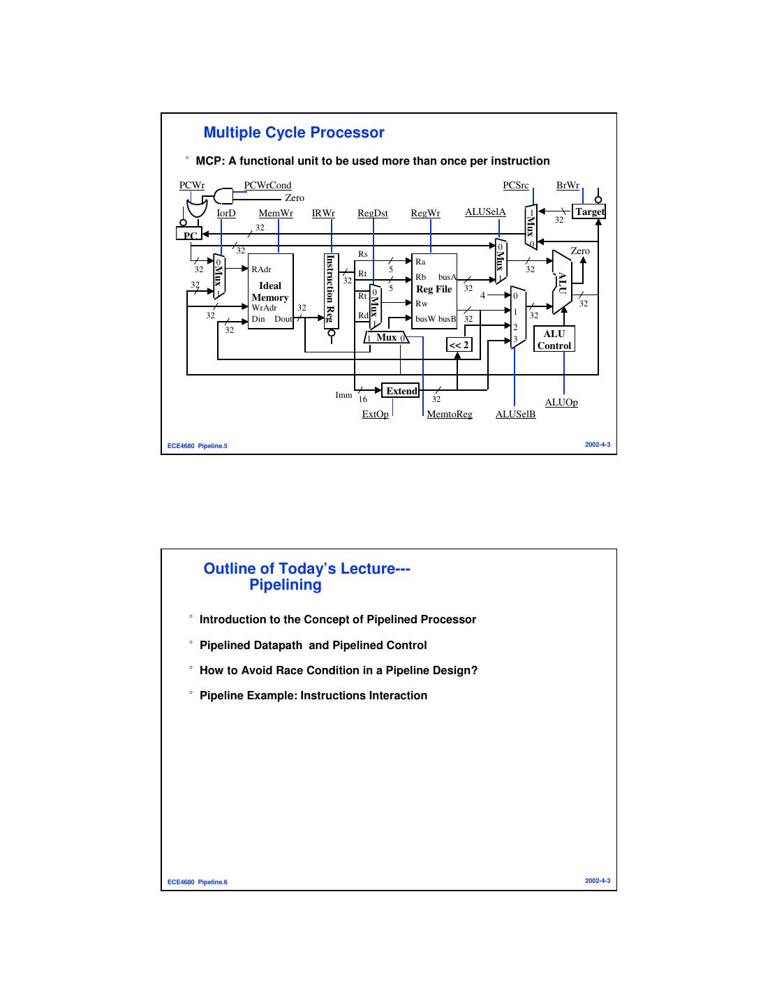
3 . Multiple Cycle Processor °MCP: A functional unit to be used more than once per instruction PCWr PCWrCond PCSrc BrWr Zero IorD MemWr IRWr RegDst RegWr ALUSelA 1 Target Mux 32 32 PC 0 0 32 Zero Mux Rs Instruction Reg 0 Ra Mux 32 RAdr Rt 5 32 ALU 32 Rb busA 1 32 Ideal 5 32 Reg File 1 Memory Rt 0 4 0 Mux WrAdr 32 Rw 32 32 Rd 1 32 Din Dout busW busB 32 1 2 32 ALU 1 Mux 0 3 << 2 Control Imm 16 Extend 32 ALUOp ExtOp MemtoReg ALUSelB ECE4680 Pipeline.5 2002-4-3 Outline of Today’s Lecture--- Pipelining °Introduction to the Concept of Pipelined Processor °Pipelined Datapath and Pipelined Control °How to Avoid Race Condition in a Pipeline Design? °Pipeline Example: Instructions Interaction ECE4680 Pipeline.6 2002-4-3
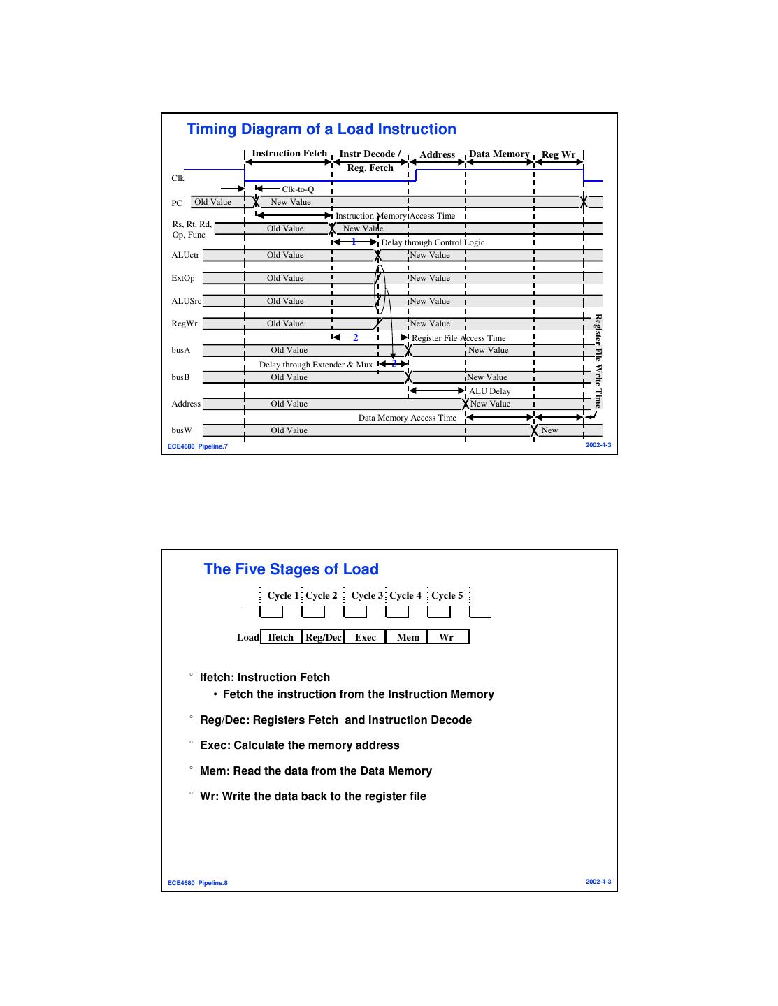
4 . Timing Diagram of a Load Instruction Instruction Fetch Instr Decode / Address Data Memory Reg Wr Reg. Fetch Clk Clk-to-Q PC Old Value New Value Instruction Memory Access Time Rs, Rt, Rd, Old Value New Value Op, Func 1 Delay through Control Logic ALUctr Old Value New Value ExtOp Old Value New Value ALUSrc Old Value New Value Register File Write Time RegWr Old Value New Value 2 Register File Access Time busA Old Value New Value Delay through Extender & Mux 3 busB Old Value New Value ALU Delay Address Old Value New Value Data Memory Access Time busW Old Value New ECE4680 Pipeline.7 2002-4-3 The Five Stages of Load Cycle 1 Cycle 2 Cycle 3 Cycle 4 Cycle 5 Load Ifetch Reg/Dec Exec Mem Wr °Ifetch: Instruction Fetch • Fetch the instruction from the Instruction Memory °Reg/Dec: Registers Fetch and Instruction Decode °Exec: Calculate the memory address °Mem: Read the data from the Data Memory °Wr: Write the data back to the register file ECE4680 Pipeline.8 2002-4-3
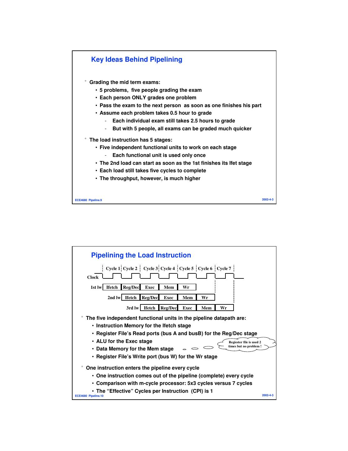
5 . Key Ideas Behind Pipelining °Grading the mid term exams: • 5 problems, five people grading the exam • Each person ONLY grades one problem • Pass the exam to the next person as soon as one finishes his part • Assume each problem takes 0.5 hour to grade - Each individual exam still takes 2.5 hours to grade - But with 5 people, all exams can be graded much quicker °The load instruction has 5 stages: • Five independent functional units to work on each stage - Each functional unit is used only once • The 2nd load can start as soon as the 1st finishes its Ifet stage • Each load still takes five cycles to complete • The throughput, however, is much higher ECE4680 Pipeline.9 2002-4-3 Pipelining the Load Instruction Cycle 1 Cycle 2 Cycle 3 Cycle 4 Cycle 5 Cycle 6 Cycle 7 Clock 1st lw Ifetch Reg/Dec Exec Mem Wr 2nd lw Ifetch Reg/Dec Exec Mem Wr 3rd lw Ifetch Reg/Dec Exec Mem Wr °The five independent functional units in the pipeline datapath are: • Instruction Memory for the Ifetch stage • Register File’s Read ports (bus A and busB) for the Reg/Dec stage • ALU for the Exec stage Regiester file is used 2 times but no problem ! • Data Memory for the Mem stage • Register File’s Write port (bus W) for the Wr stage °One instruction enters the pipeline every cycle • One instruction comes out of the pipeline (complete) every cycle • Comparison with m-cycle processor: 5x3 cycles versus 7 cycles • The “Effective” Cycles per Instruction (CPI) is 1 ECE4680 Pipeline.10 2002-4-3
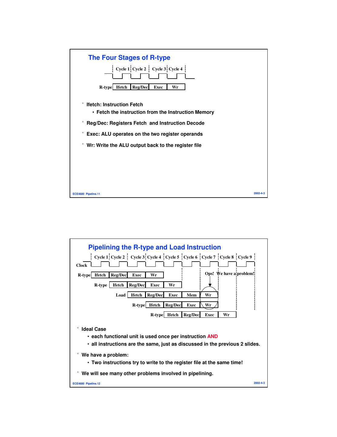
6 . The Four Stages of R-type Cycle 1 Cycle 2 Cycle 3 Cycle 4 R-type Ifetch Reg/Dec Exec Wr °Ifetch: Instruction Fetch • Fetch the instruction from the Instruction Memory °Reg/Dec: Registers Fetch and Instruction Decode °Exec: ALU operates on the two register operands °Wr: Write the ALU output back to the register file ECE4680 Pipeline.11 2002-4-3 Pipelining the R-type and Load Instruction Cycle 1 Cycle 2 Cycle 3 Cycle 4 Cycle 5 Cycle 6 Cycle 7 Cycle 8 Cycle 9 Clock R-type Ifetch Reg/Dec Exec Wr Ops! We have a problem! R-type Ifetch Reg/Dec Exec Wr Load Ifetch Reg/Dec Exec Mem Wr R-type Ifetch Reg/Dec Exec Wr R-type Ifetch Reg/Dec Exec Wr °Ideal Case • each functional unit is used once per instruction AND • all instructions are the same, just as discussed in the previous 2 slides. °We have a problem: • Two instructions try to write to the register file at the same time! °We will see many other problems involved in pipelining. ECE4680 Pipeline.12 2002-4-3
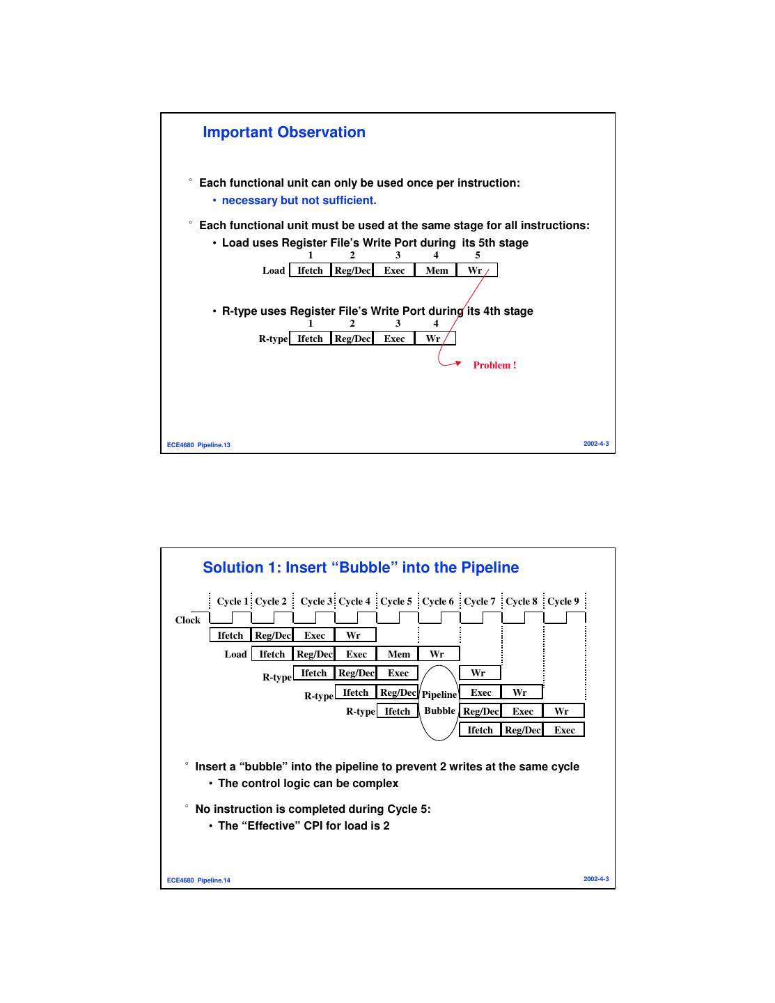
7 . Important Observation °Each functional unit can only be used once per instruction: • necessary but not sufficient. °Each functional unit must be used at the same stage for all instructions: • Load uses Register File’s Write Port during its 5th stage 1 2 3 4 5 Load Ifetch Reg/Dec Exec Mem Wr • R-type uses Register File’s Write Port during its 4th stage 1 2 3 4 R-type Ifetch Reg/Dec Exec Wr Problem ! ECE4680 Pipeline.13 2002-4-3 Solution 1: Insert “Bubble” into the Pipeline Cycle 1 Cycle 2 Cycle 3 Cycle 4 Cycle 5 Cycle 6 Cycle 7 Cycle 8 Cycle 9 Clock Ifetch Reg/Dec Exec Wr Load Ifetch Reg/Dec Exec Mem Wr R-type Ifetch Reg/Dec Exec Wr Wr R-type Ifetch Reg/Dec Pipeline Exec Exec Wr Wr Bubble R-type Ifetch Reg/Dec Reg/Dec Exec Exec Wr Wr Ifetch Ifetch Reg/Dec Reg/Dec Exec Exec °Insert a “bubble” into the pipeline to prevent 2 writes at the same cycle • The control logic can be complex °No instruction is completed during Cycle 5: • The “Effective” CPI for load is 2 ECE4680 Pipeline.14 2002-4-3
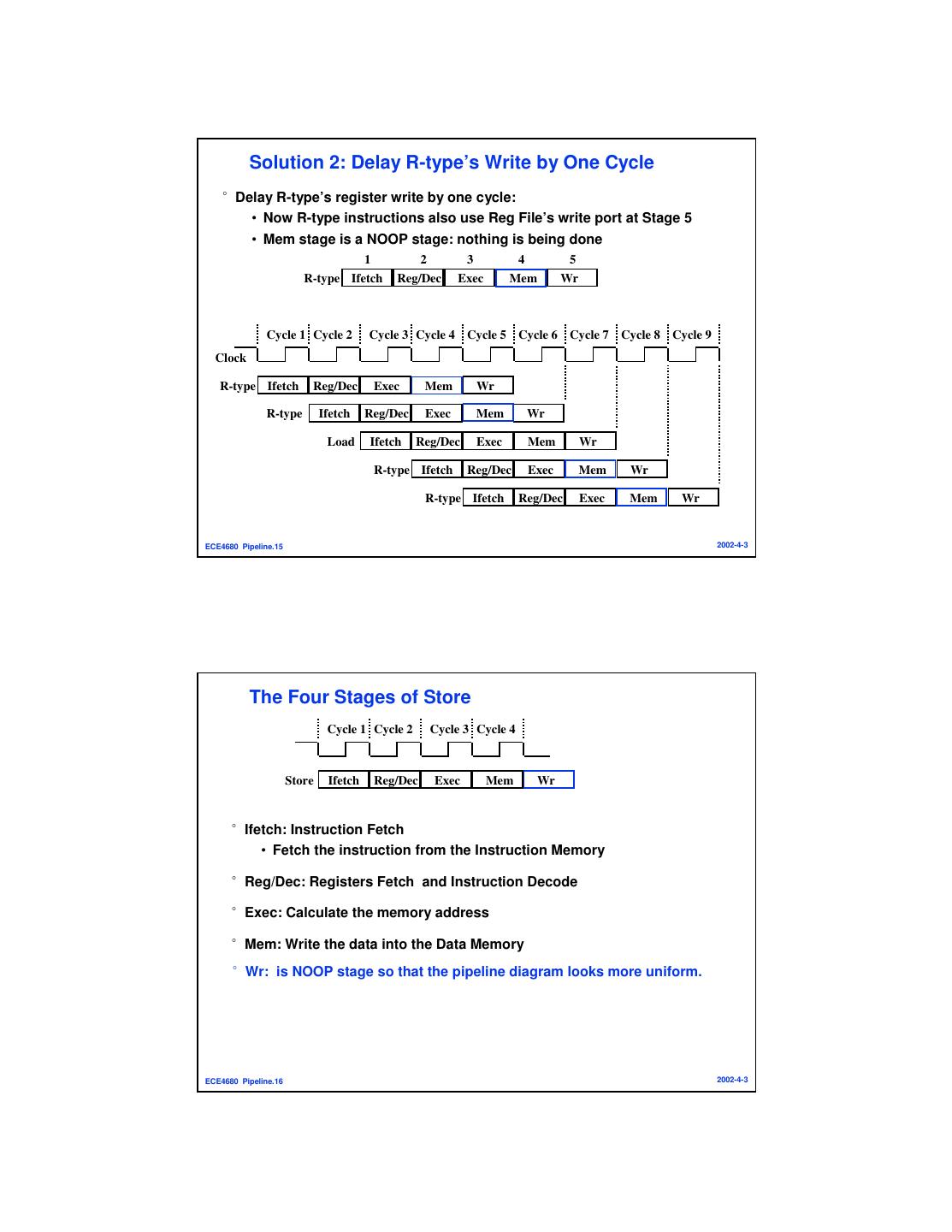
8 . Solution 2: Delay R-type’s Write by One Cycle °Delay R-type’s register write by one cycle: • Now R-type instructions also use Reg File’s write port at Stage 5 • Mem stage is a NOOP stage: nothing is being done 1 2 3 4 5 R-type Ifetch Reg/Dec Exec Mem Wr Cycle 1 Cycle 2 Cycle 3 Cycle 4 Cycle 5 Cycle 6 Cycle 7 Cycle 8 Cycle 9 Clock R-type Ifetch Reg/Dec Exec Mem Wr R-type Ifetch Reg/Dec Exec Mem Wr Load Ifetch Reg/Dec Exec Mem Wr R-type Ifetch Reg/Dec Exec Mem Wr R-type Ifetch Reg/Dec Exec Mem Wr ECE4680 Pipeline.15 2002-4-3 The Four Stages of Store Cycle 1 Cycle 2 Cycle 3 Cycle 4 Store Ifetch Reg/Dec Exec Mem Wr °Ifetch: Instruction Fetch • Fetch the instruction from the Instruction Memory °Reg/Dec: Registers Fetch and Instruction Decode °Exec: Calculate the memory address °Mem: Write the data into the Data Memory °Wr: is NOOP stage so that the pipeline diagram looks more uniform. ECE4680 Pipeline.16 2002-4-3
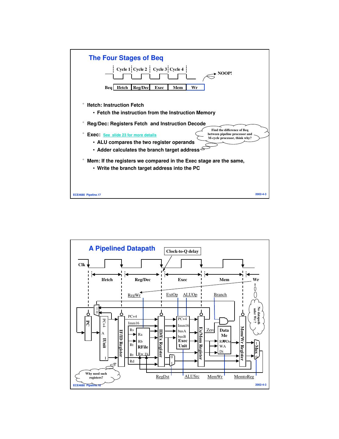
9 . The Four Stages of Beq Cycle 1 Cycle 2 Cycle 3 Cycle 4 NOOP! Beq Ifetch Reg/Dec Exec Mem Wr °Ifetch: Instruction Fetch • Fetch the instruction from the Instruction Memory °Reg/Dec: Registers Fetch and Instruction Decode Find the difference of Beq °Exec: See slide 23 for more details between pipeline processor and M-cycle processor, think why? • ALU compares the two register operands • Adder calculates the branch target address °Mem: If the registers we compared in the Exec stage are the same, • Write the branch target address into the PC ECE4680 Pipeline.17 2002-4-3 A Pipelined Datapath Clock-to-Q delay Clk Ifetch Reg/Dec Exec Mem Wr RegWr ExtOp ALUOp Branch No datapath 1 uder Wr ? 0 PC+4 PC+4 PC+4 PC Imm16 Imm16 Mem/Wr Register Ex/Mem Register Rs Zero Data ID/Ex Register busA IF/ID Register A Ra busB Me IUnit Rb Exec mDo RA Rt 1 Unit Mux RFile WA Di Rt Rw Di I 0 0 Rd 1 Why need such registers? RegDst ALUSrc MemWr MemtoReg ECE4680 Pipeline.18 2002-4-3
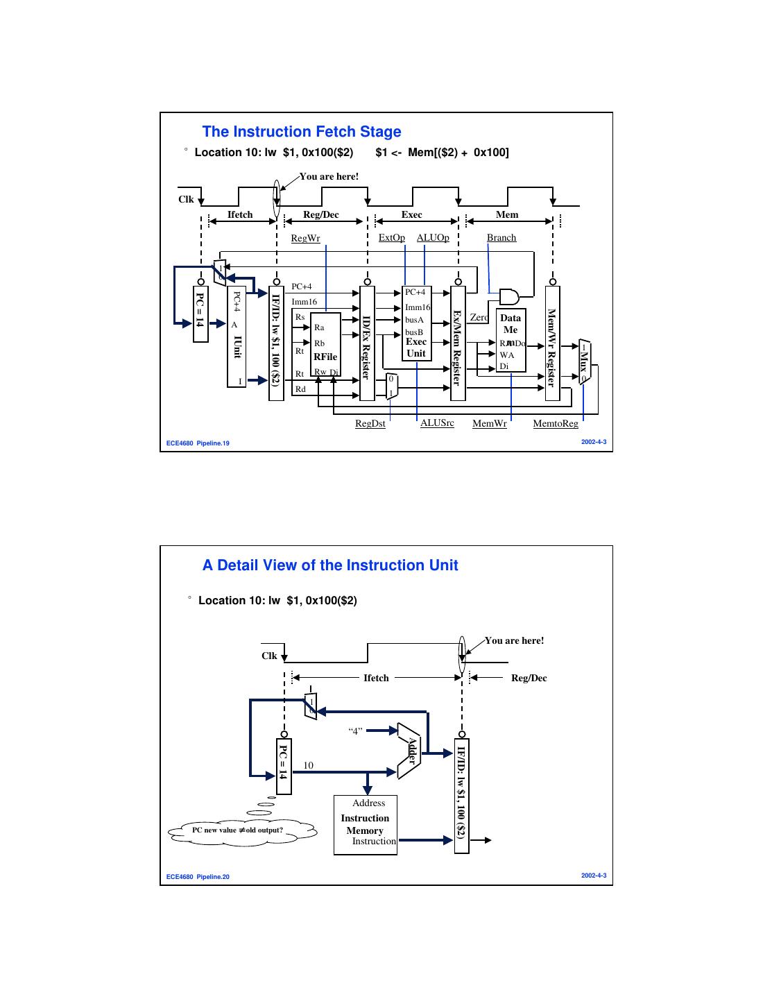
10 . The Instruction Fetch Stage °Location 10: lw $1, 0x100($2) $1 <- Mem[($2) + 0x100] You are here! Clk Ifetch Reg/Dec Exec Mem RegWr ExtOp ALUOp Branch 1 0 PC+4 PC+4 PC+4 PC = 14 IF/ID: lw $1, 100 ($2) Imm16 Imm16 Mem/Wr Register Ex/Mem Register Rs Zero Data ID/Ex Register busA A Ra busB Me IUnit Rb Exec mDo RA Rt 1 Unit Mux RFile WA Di Rt Rw Di I 0 0 Rd 1 RegDst ALUSrc MemWr MemtoReg ECE4680 Pipeline.19 2002-4-3 A Detail View of the Instruction Unit °Location 10: lw $1, 0x100($2) You are here! Clk Ifetch Reg/Dec 1 0 “4” Adder PC = 14 IF/ID: lw $1, 100 ($2) 10 Address Instruction PC new value ≠old output? Memory Instruction ECE4680 Pipeline.20 2002-4-3
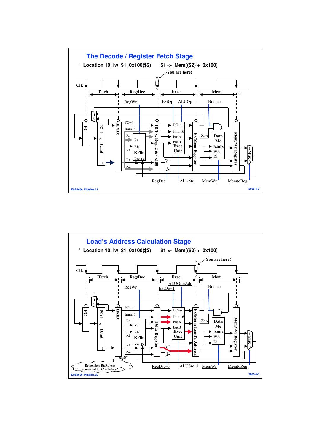
11 . The Decode / Register Fetch Stage °Location 10: lw $1, 0x100($2) $1 <- Mem[($2) + 0x100] You are here! Clk Ifetch Reg/Dec Exec Mem RegWr ExtOp ALUOp Branch 1 0 PC+4 IF/ID: PC+4 PC+4 ID/Ex: Reg. 2 & 0x100 PC Imm16 Imm16 Mem/Wr Register Ex/Mem Register Rs busA Zero Data A Ra busB Me IUnit Rb Exec mDo RA Rt 1 Unit Mux RFile WA Di Rt Rw Di I 0 0 Rd 1 RegDst ALUSrc MemWr MemtoReg ECE4680 Pipeline.21 2002-4-3 Load’s Address Calculation Stage °Location 10: lw $1, 0x100($2) $1 <- Mem[($2) + 0x100] You are here! Clk Ifetch Reg/Dec Exec Mem ALUOp=Add RegWr ExtOp=1 Branch 1 0 PC+4 IF/ID: Ex/Mem: Load’s Address PC+4 PC+4 PC Imm16 Imm16 Mem/Wr Register Rs Zero Data ID/Ex Register busA A Ra busB Me IUnit Rb Exec mDo RA Rt 1 Unit Mux RFile WA Di Rt Rw Di I 0 0 Rd 1 Remember Rt/Rd was RegDst=0 ALUSrc=1 MemWr MemtoReg connected to Rfile before? ECE4680 Pipeline.22 2002-4-3
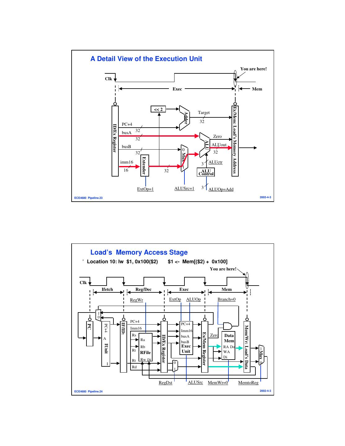
12 . A Detail View of the Execution Unit You are here! Clk Exec Mem Ex/Mem: Load’s Memory Address << 2 Target Adder 32 PC+4 ID/Ex Register busA 32 Zero 32 ALU busB ALUout 0 32 32 Mux Extender imm16 3 ALUctr 1 16 32 ALU Control ExtOp=1 ALUSrc=1 3 ALUOp=Add ECE4680 Pipeline.23 2002-4-3 Load’s Memory Access Stage °Location 10: lw $1, 0x100($2) $1 <- Mem[($2) + 0x100] You are here! Clk Ifetch Reg/Dec Exec Mem RegWr ExtOp ALUOp Branch=0 1 0 PC+4 IF/ID: PC+4 PC+4 PC Mem/Wr: Load’s Data Imm16 Imm16 Ex/Mem Register Rs Zero Data ID/Ex Register busA A Ra busB Mem IUnit Rb Exec RA Do Rt 1 Unit Mux RFile WA Di Rt Rw Di I 0 0 Rd 1 RegDst ALUSrc MemWr=0 MemtoReg ECE4680 Pipeline.24 2002-4-3
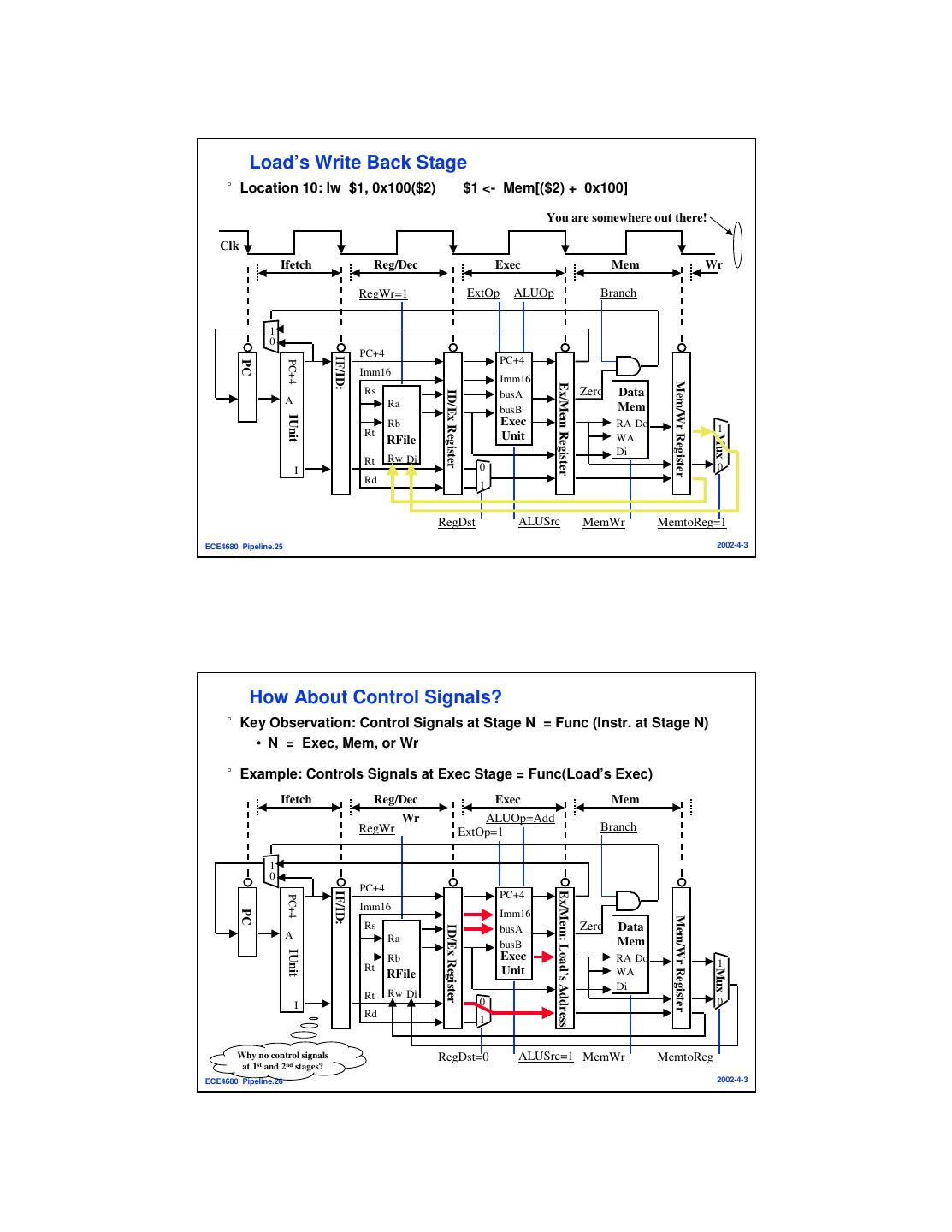
13 . Load’s Write Back Stage °Location 10: lw $1, 0x100($2) $1 <- Mem[($2) + 0x100] You are somewhere out there! Clk Ifetch Reg/Dec Exec Mem Wr RegWr=1 ExtOp ALUOp Branch 1 0 PC+4 IF/ID: PC+4 PC+4 PC Imm16 Imm16 Mem/Wr Register Ex/Mem Register Rs Zero Data ID/Ex Register busA A Ra busB Mem IUnit Rb Exec RA Do Rt 1 Unit Mux RFile WA Di Rt Rw Di I 0 0 Rd 1 RegDst ALUSrc MemWr MemtoReg=1 ECE4680 Pipeline.25 2002-4-3 How About Control Signals? °Key Observation: Control Signals at Stage N = Func (Instr. at Stage N) • N = Exec, Mem, or Wr °Example: Controls Signals at Exec Stage = Func(Load’s Exec) Ifetch Reg/Dec Exec Mem Wr ALUOp=Add RegWr ExtOp=1 Branch 1 0 PC+4 IF/ID: Ex/Mem: Load’s Address PC+4 PC+4 Imm16 PC Imm16 Mem/Wr Register Rs Zero Data ID/Ex Register busA A Ra busB Mem IUnit Rb Exec RA Do Rt 1 Unit Mux RFile WA Di Rt Rw Di I 0 0 Rd 1 Why no control signals RegDst=0 ALUSrc=1 MemWr MemtoReg at 1st and 2nd stages? ECE4680 Pipeline.26 2002-4-3
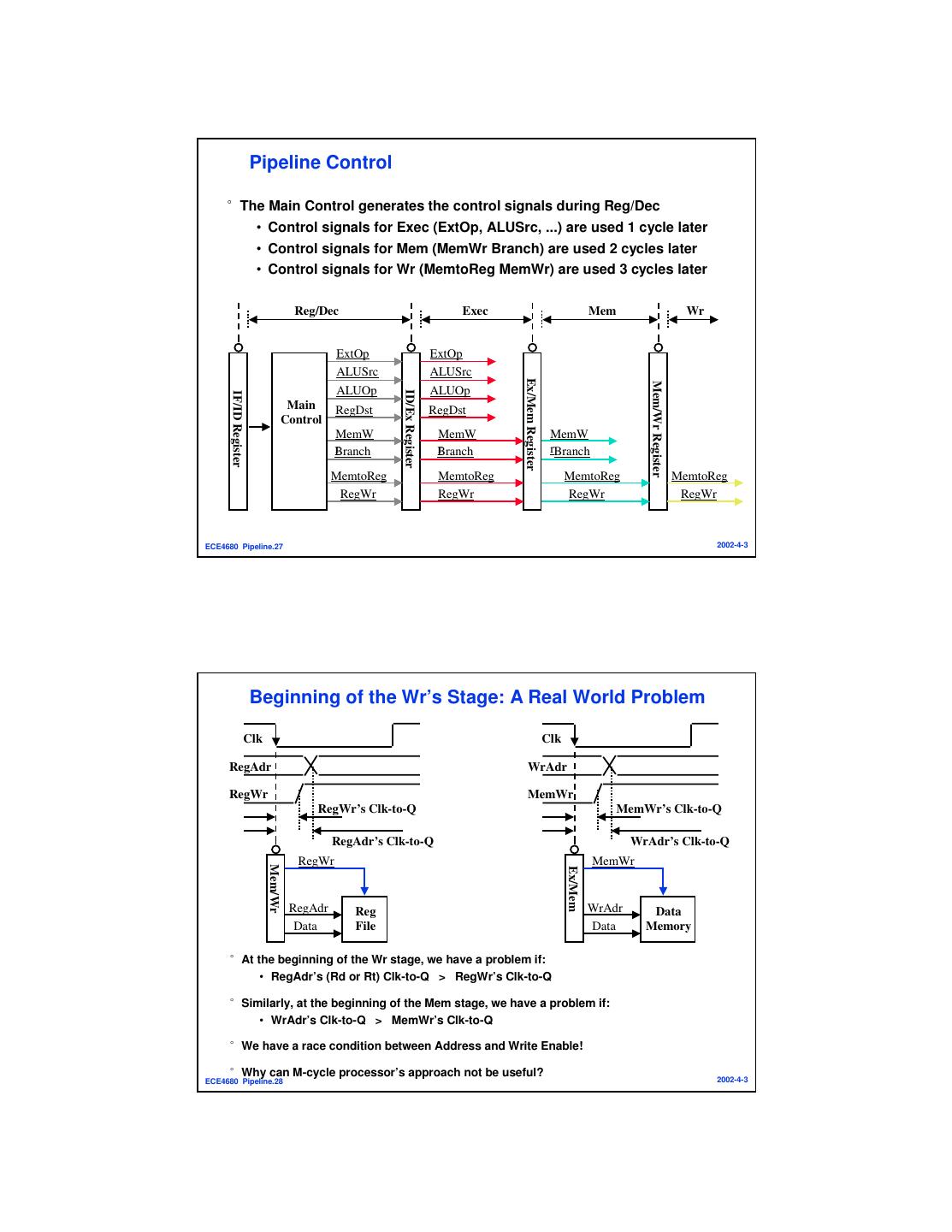
14 . Pipeline Control °The Main Control generates the control signals during Reg/Dec • Control signals for Exec (ExtOp, ALUSrc, ...) are used 1 cycle later • Control signals for Mem (MemWr Branch) are used 2 cycles later • Control signals for Wr (MemtoReg MemWr) are used 3 cycles later Reg/Dec Exec Mem Wr ExtOp ExtOp ALUSrc ALUSrc Ex/Mem Register Mem/Wr Register ALUOp ALUOp ID/Ex Register IF/ID Register Main RegDst RegDst Control MemW MemW MemW r Branch r Branch rBranch MemtoReg MemtoReg MemtoReg MemtoReg RegWr RegWr RegWr RegWr ECE4680 Pipeline.27 2002-4-3 Beginning of the Wr’s Stage: A Real World Problem Clk Clk RegAdr WrAdr RegWr MemWr RegWr’s Clk-to-Q MemWr’s Clk-to-Q RegAdr’s Clk-to-Q WrAdr’s Clk-to-Q RegWr MemWr Mem/Wr Ex/Mem RegAdr Reg WrAdr Data Data File Data Memory °At the beginning of the Wr stage, we have a problem if: • RegAdr’s (Rd or Rt) Clk-to-Q > RegWr’s Clk-to-Q °Similarly, at the beginning of the Mem stage, we have a problem if: • WrAdr’s Clk-to-Q > MemWr’s Clk-to-Q °We have a race condition between Address and Write Enable! °Why can M-cycle processor’s approach not be useful? ECE4680 Pipeline.28 2002-4-3
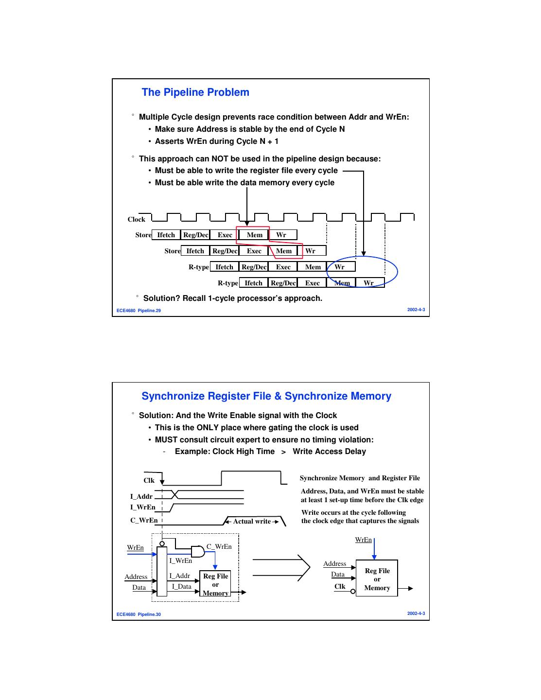
15 . The Pipeline Problem °Multiple Cycle design prevents race condition between Addr and WrEn: • Make sure Address is stable by the end of Cycle N • Asserts WrEn during Cycle N + 1 °This approach can NOT be used in the pipeline design because: • Must be able to write the register file every cycle • Must be able write the data memory every cycle Clock Store Ifetch Reg/Dec Exec Mem Wr Store Ifetch Reg/Dec Exec Mem Wr R-type Ifetch Reg/Dec Exec Mem Wr R-type Ifetch Reg/Dec Exec Mem Wr °Solution? Recall 1-cycle processor’s approach. ECE4680 Pipeline.29 2002-4-3 Synchronize Register File & Synchronize Memory °Solution: And the Write Enable signal with the Clock • This is the ONLY place where gating the clock is used • MUST consult circuit expert to ensure no timing violation: - Example: Clock High Time > Write Access Delay Clk Synchronize Memory and Register File Address, Data, and WrEn must be stable I_Addr at least 1 set-up time before the Clk edge I_WrEn Write occurs at the cycle following C_WrEn Actual write the clock edge that captures the signals WrEn WrEn C_WrEn I_WrEn Address Data Reg File Address I_Addr Reg File or Data I_Data or Clk Memory Memory ECE4680 Pipeline.30 2002-4-3
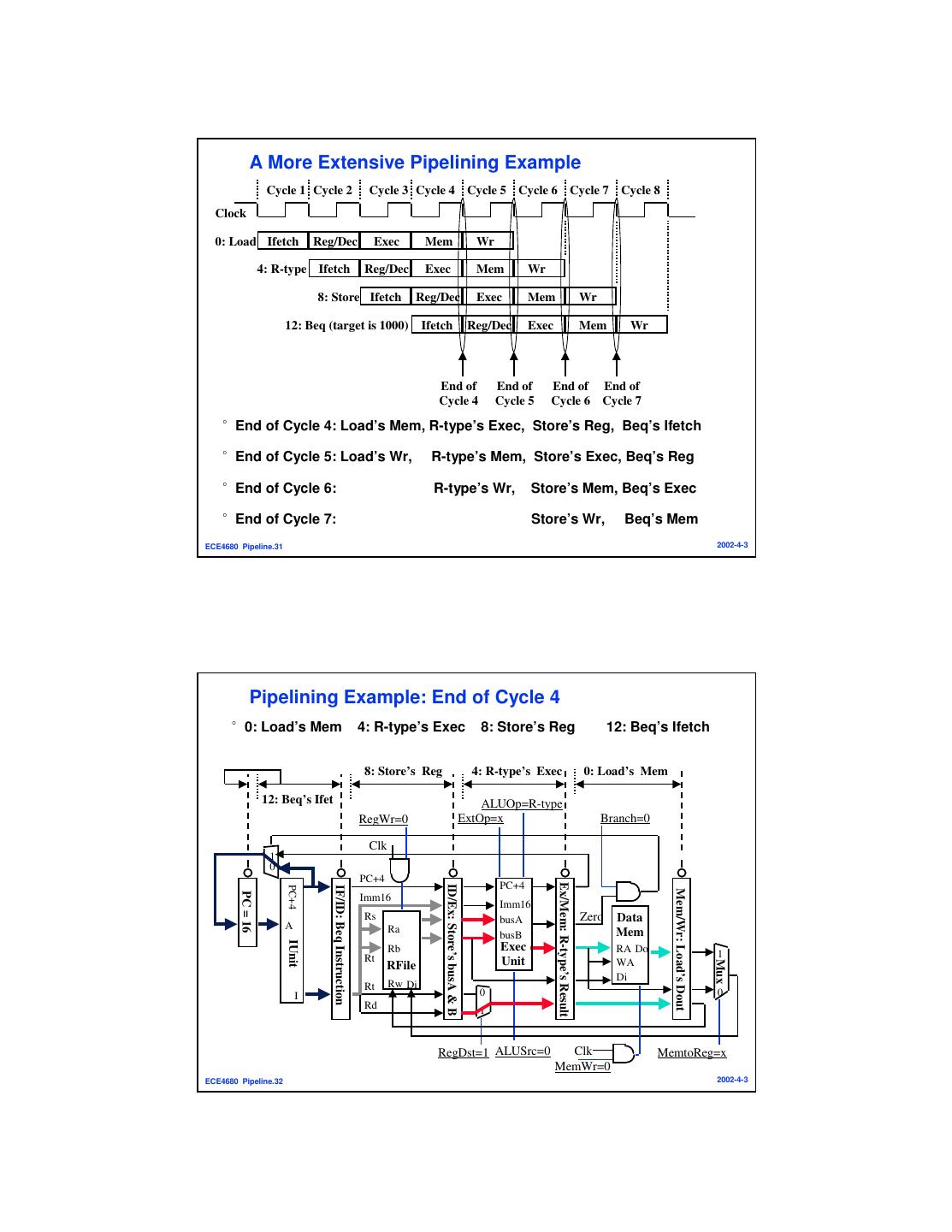
16 . A More Extensive Pipelining Example Cycle 1 Cycle 2 Cycle 3 Cycle 4 Cycle 5 Cycle 6 Cycle 7 Cycle 8 Clock 0: Load Ifetch Reg/Dec Exec Mem Wr 4: R-type Ifetch Reg/Dec Exec Mem Wr 8: Store Ifetch Reg/Dec Exec Mem Wr 12: Beq (target is 1000) Ifetch Reg/Dec Exec Mem Wr End of End of End of End of Cycle 4 Cycle 5 Cycle 6 Cycle 7 °End of Cycle 4: Load’s Mem, R-type’s Exec, Store’s Reg, Beq’s Ifetch °End of Cycle 5: Load’s Wr, R-type’s Mem, Store’s Exec, Beq’s Reg °End of Cycle 6: R-type’s Wr, Store’s Mem, Beq’s Exec °End of Cycle 7: Store’s Wr, Beq’s Mem ECE4680 Pipeline.31 2002-4-3 Pipelining Example: End of Cycle 4 °0: Load’s Mem 4: R-type’s Exec 8: Store’s Reg 12: Beq’s Ifetch 8: Store’s Reg 4: R-type’s Exec 0: Load’s Mem 12: Beq’s Ifet ALUOp=R-type RegWr=0 ExtOp=x Branch=0 Clk 1 0 PC+4 PC+4 Ex/Mem: R-type’s Result ID/Ex: Store’s busA & B PC+4 IF/ID: Beq Instruction Mem/Wr: Load’s Dout PC = 16 Imm16 Imm16 Rs busA Zero Data A Ra busB Mem IUnit Rb Exec RA Do Rt 1 Unit Mux RFile WA Di Rt Rw Di I 0 0 Rd 1 RegDst=1 ALUSrc=0 Clk MemtoReg=x MemWr=0 ECE4680 Pipeline.32 2002-4-3
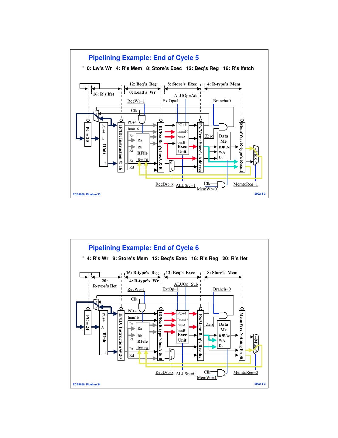
17 . Pipelining Example: End of Cycle 5 °0: Lw’s Wr 4: R’s Mem 8: Store’s Exec 12: Beq’s Reg 16: R’s Ifetch 12: Beq’s Reg 8: Store’s Exec 4: R-type’s Mem 16: R’s Ifet 0: Load’s Wr ALUOp=Add RegWr=1 ExtOp=1 Branch=0 Clk 1 0 PC+4 Mem/Wr: R-type’s Result Ex/Mem: Store’s Address PC+4 PC+4 IF/ID: Instruction @ 16 ID/Ex: Beq’s busA & B PC = 20 Imm16 Imm16 Rs busA Zero Data A Ra busB Me IUnit Rb Exec mDo RA Rt 1 Unit Mux RFile WA Di Rt Rw Di I 0 0 Rd 1 RegDst=x ALUSrc=1 Clk MemtoReg=1 MemWr=0 ECE4680 Pipeline.33 2002-4-3 Pipelining Example: End of Cycle 6 °4: R’s Wr 8: Store’s Mem 12: Beq’s Exec 16: R’s Reg 20: R’s Ifet 16: R-type’s Reg 12: Beq’s Exec 8: Store’s Mem 20: 4: R-type’s Wr R-type’s Ifet ALUOp=Sub RegWr=1 ExtOp=1 Branch=0 Clk 1 0 PC+4 ID/Ex:R-type’s busA & B PC+4 Mem/Wr: Nothing for St PC+4 IF/ID: Instruction @ 20 Ex/Mem: Beq’s Results PC = 24 Imm16 Imm16 Rs busA Zero Data A Ra busB Me IUnit Rb Exec mDo RA Rt 1 Unit Mux RFile WA Di Rt Rw Di I 0 0 Rd 1 RegDst=x ALUSrc=0 Clk MemtoReg=0 MemWr=1 ECE4680 Pipeline.34 2002-4-3
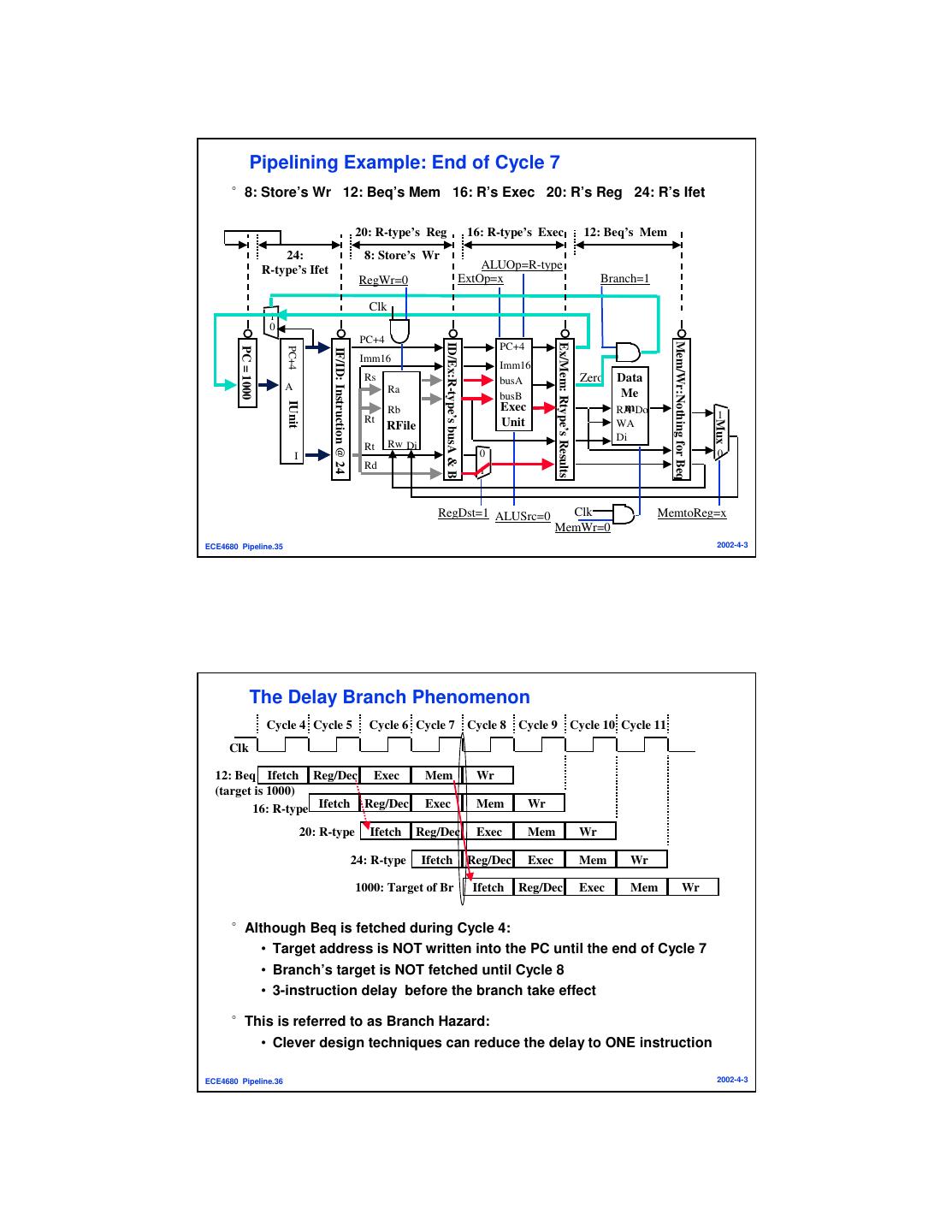
18 . Pipelining Example: End of Cycle 7 °8: Store’s Wr 12: Beq’s Mem 16: R’s Exec 20: R’s Reg 24: R’s Ifet 20: R-type’s Reg 16: R-type’s Exec 12: Beq’s Mem 24: 8: Store’s Wr R-type’s Ifet ALUOp=R-type RegWr=0 ExtOp=x Branch=1 Clk 1 0 PC+4 Mem/Wr:Nothing for Beq ID/Ex:R-type’s busA & B PC+4 Ex/Mem: Rtype’s Results PC = 1000 PC+4 IF/ID: Instruction @ 24 Imm16 Imm16 Rs busA Zero Data A Ra busB Me IUnit Rb Exec mDo RA Rt 1 Unit Mux RFile WA Di Rt Rw Di I 0 0 Rd 1 RegDst=1 ALUSrc=0 Clk MemtoReg=x MemWr=0 ECE4680 Pipeline.35 2002-4-3 The Delay Branch Phenomenon Cycle 4 Cycle 5 Cycle 6 Cycle 7 Cycle 8 Cycle 9 Cycle 10 Cycle 11 Clk 12: Beq Ifetch Reg/Dec Exec Mem Wr (target is 1000) 16: R-type Ifetch Reg/Dec Exec Mem Wr 20: R-type Ifetch Reg/Dec Exec Mem Wr 24: R-type Ifetch Reg/Dec Exec Mem Wr 1000: Target of Br Ifetch Reg/Dec Exec Mem Wr °Although Beq is fetched during Cycle 4: • Target address is NOT written into the PC until the end of Cycle 7 • Branch’s target is NOT fetched until Cycle 8 • 3-instruction delay before the branch take effect °This is referred to as Branch Hazard: • Clever design techniques can reduce the delay to ONE instruction ECE4680 Pipeline.36 2002-4-3
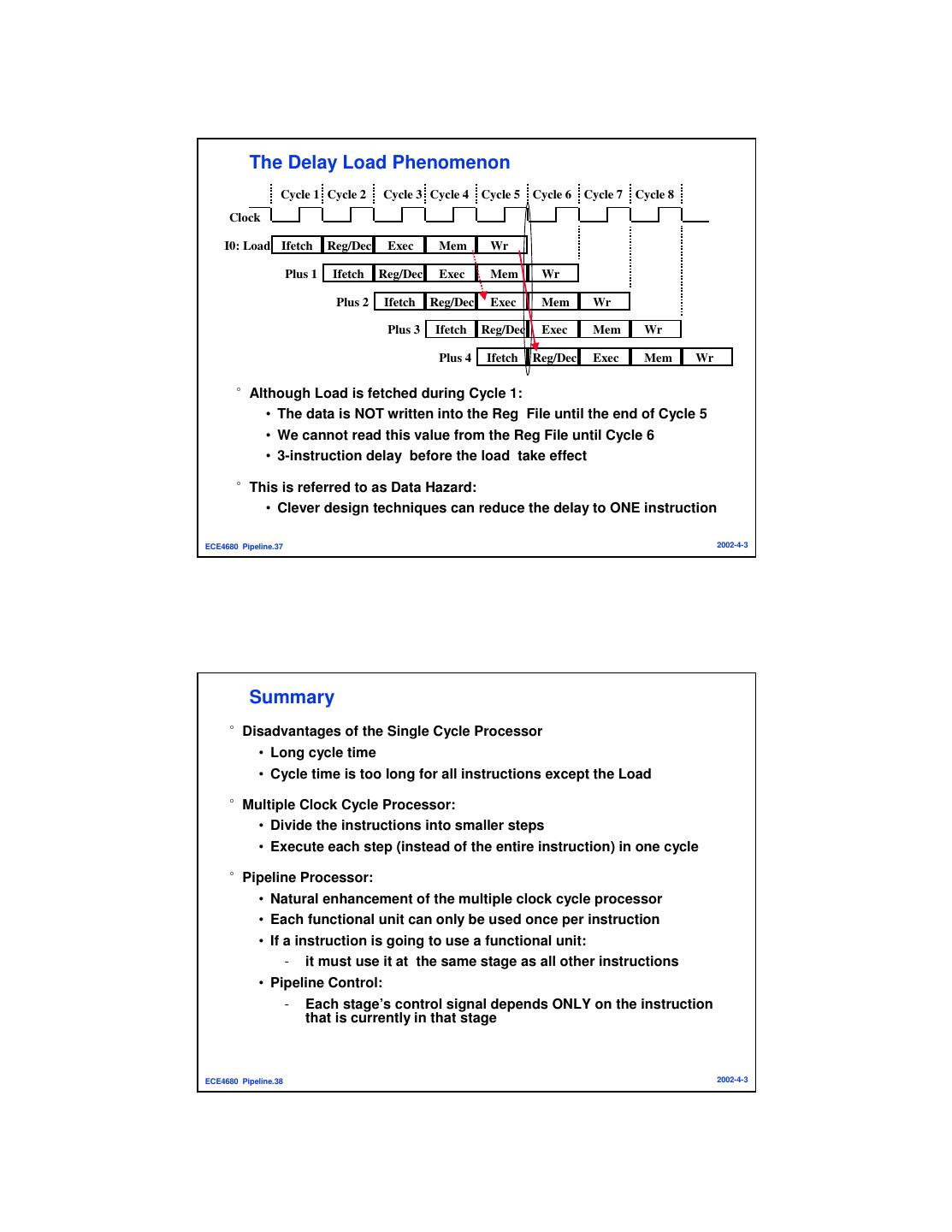
19 . The Delay Load Phenomenon Cycle 1 Cycle 2 Cycle 3 Cycle 4 Cycle 5 Cycle 6 Cycle 7 Cycle 8 Clock I0: Load Ifetch Reg/Dec Exec Mem Wr Plus 1 Ifetch Reg/Dec Exec Mem Wr Plus 2 Ifetch Reg/Dec Exec Mem Wr Plus 3 Ifetch Reg/Dec Exec Mem Wr Plus 4 Ifetch Reg/Dec Exec Mem Wr °Although Load is fetched during Cycle 1: • The data is NOT written into the Reg File until the end of Cycle 5 • We cannot read this value from the Reg File until Cycle 6 • 3-instruction delay before the load take effect °This is referred to as Data Hazard: • Clever design techniques can reduce the delay to ONE instruction ECE4680 Pipeline.37 2002-4-3 Summary °Disadvantages of the Single Cycle Processor • Long cycle time • Cycle time is too long for all instructions except the Load °Multiple Clock Cycle Processor: • Divide the instructions into smaller steps • Execute each step (instead of the entire instruction) in one cycle °Pipeline Processor: • Natural enhancement of the multiple clock cycle processor • Each functional unit can only be used once per instruction • If a instruction is going to use a functional unit: - it must use it at the same stage as all other instructions • Pipeline Control: - Each stage’s control signal depends ONLY on the instruction that is currently in that stage ECE4680 Pipeline.38 2002-4-3
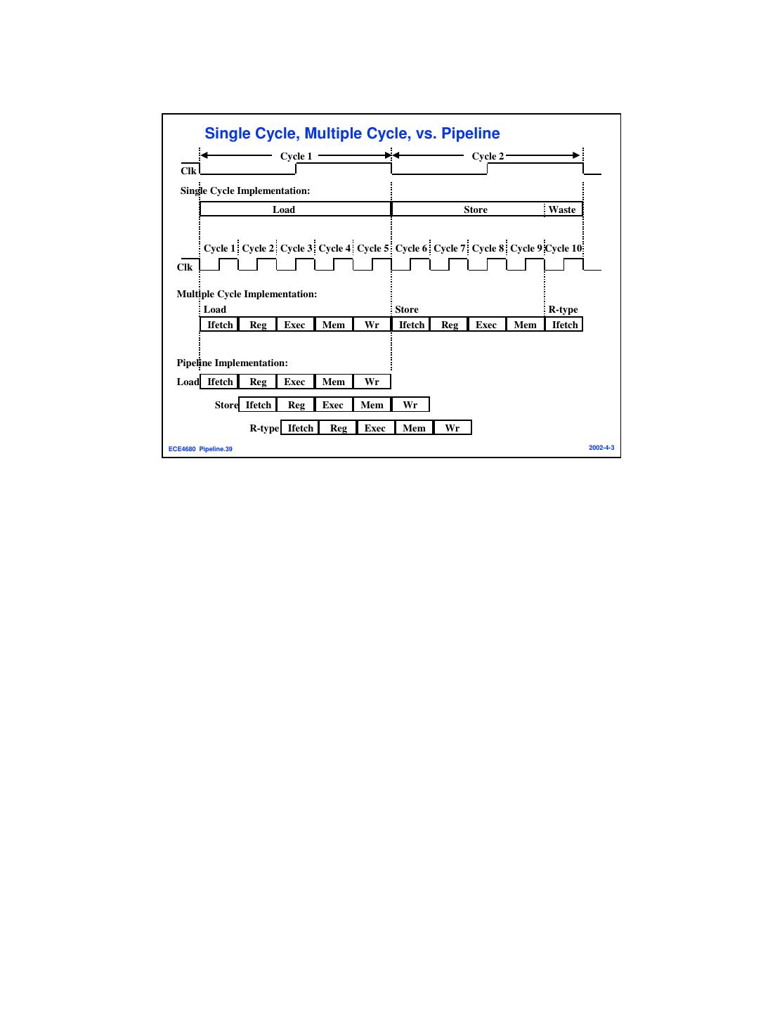
20 . Single Cycle, Multiple Cycle, vs. Pipeline Cycle 1 Cycle 2 Clk Single Cycle Implementation: Load Store Waste Cycle 1 Cycle 2 Cycle 3 Cycle 4 Cycle 5 Cycle 6 Cycle 7 Cycle 8 Cycle 9 Cycle 10 Clk Multiple Cycle Implementation: Load Store R-type Ifetch Reg Exec Mem Wr Ifetch Reg Exec Mem Ifetch Pipeline Implementation: Load Ifetch Reg Exec Mem Wr Store Ifetch Reg Exec Mem Wr R-type Ifetch Reg Exec Mem Wr ECE4680 Pipeline.39 2002-4-3


