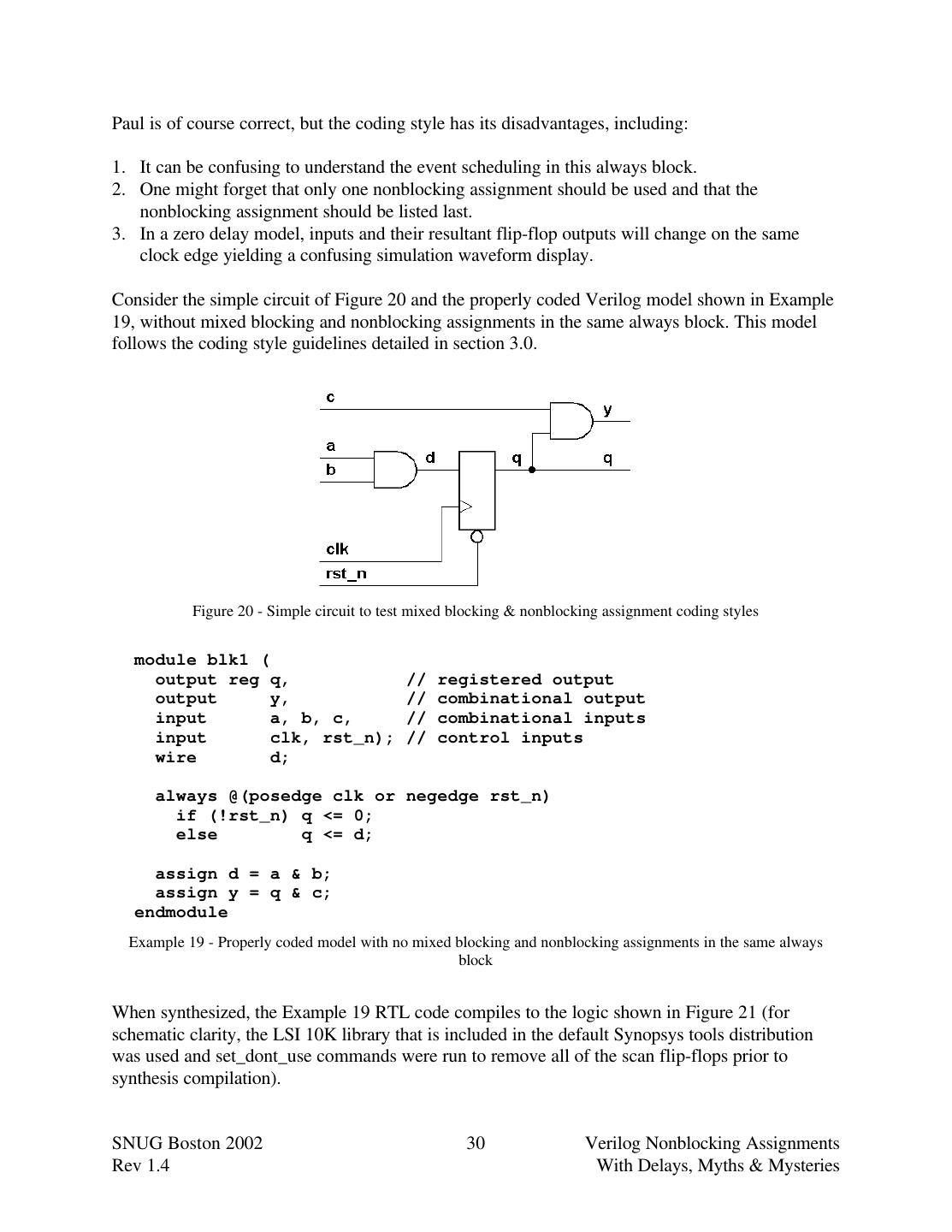
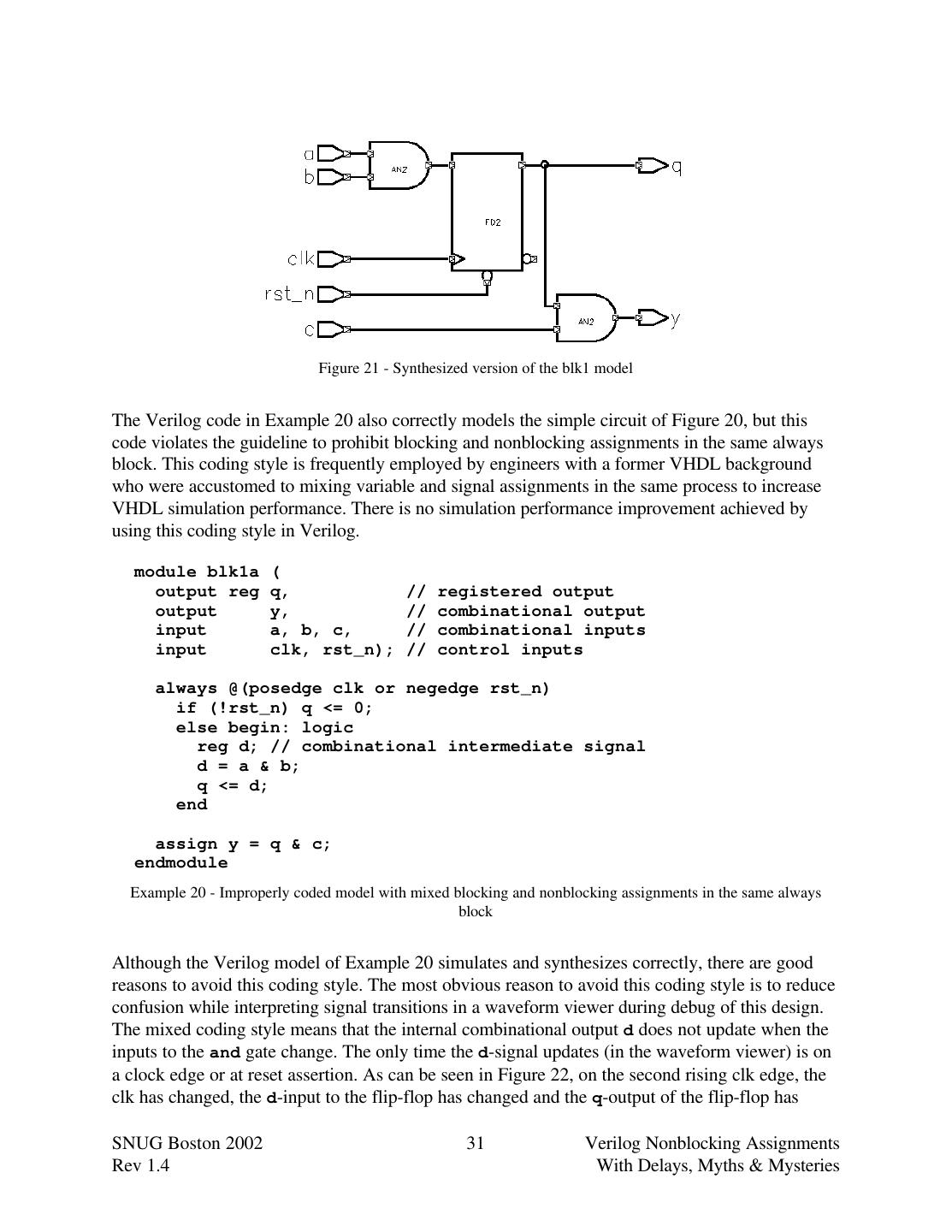
- 快召唤伙伴们来围观吧
- 微博 QQ QQ空间 贴吧
- 文档嵌入链接
- 复制
- 微信扫一扫分享
- 已成功复制到剪贴板
Cummings SNUG2002 Boston NBA with Delays
展开查看详情
1 . Verilog Nonblocking Assignments With Delays, Myths & Mysteries Clifford E. Cummings SNUG-2002 Boston, MA Voted Best Paper 2nd Place Sunburst Design, Inc. cliffc@sunburst-design.com ABSTRACT There is a common misconception that coding sequential logic with nonblocking assignments does not simulate correctly unless a #1 delay is added to the right hand side of the nonblocking assignment operator. This is not true. This paper will explain how delays and nonblocking assignments impact the Verilog event queue. This paper will also detail both good and bad reasons for adding delays to nonblocking assignments and include guidelines for good RTL coding styles that permit mixed RTL and gate-level simulation.
2 .1.0 Introduction In his book Writing Testbenches[7], Functional Verification of HDL Models, Janick Bergeron claims that VHDL and Verilog both have the same area under the learning curve[8]. Due to the misinformation that has been spread through numerous Verilog books and training courses, I am afraid Bergeron may be right. When Verilog is taught correctly, I believe the area under the Verilog learning curve is much smaller and Verilog simulations run much faster than comparable VHDL simulations. This paper details functionality and important guidelines related to nonblocking assignments and nonblocking assignments with delays. Before discussing nonblocking assignment functionality and recommendations, a quick review of the definition of nonblocking assignments is in order: A nonblocking assignment is a Verilog procedural assignment that uses the "<=" operator inside of a procedural block. It is illegal to use a nonblocking assignment in a continuous assignment statement or in a net declaration. A nonblocking assignment can be viewed as a 2-step assignment. At the beginning of a simulation time step, the right-hand-side (RHS) of the nonblocking assignment is (1) evaluated and at the end of the nonblocking assignment the left-hand-side (LHS) variable is (2) updated. A nonblocking assignment does not "block" other assignments from being executed between the evaluation and update steps of a nonblocking assignment; hence, the name "nonblocking." Despite complaints from commercial document spell-checking software, nonblocking is spelled without a hyphen, as noted in both IEEE Verilog Standards[4][5] and the pending IEEE Verilog Synthesis Standard[6]. SNUG Boston 2002 2 Verilog Nonblocking Assignments Rev 1.4 With Delays, Myths & Mysteries
3 .2.0 The Verilog event queue The Verilog event queue described in this paper is an algorithmic description. The exact implementation is not defined in the Verilog Standard but the outcome must duplicate the functionality of the description. Section 5.4 of both IEEE Verilog Standards documents, IEEE Std 1364-1995[4] and IEEE Std 1364-2001[5], describes "The Verilog simulation reference model." The reference model is shown below: In all the examples that follow, T refers to the current simulation time, and all events are held in the event queue, ordered by simulation time. while (there are events) { if (no active events) { if (there are inactive events) { activate all inactive events; } else if (there are nonblocking assign update events) { activate all nonblocking assign update events; } else if (there are monitor events) { activate all monitor events; } else { advance T to the next event time; activate all inactive events for time T; } } E = any active event; if (E is an update event) { update the modified object; add evaluation events for sensitive processes to event queue; } else { /* shall be an evaluation event */ evaluate the process; add update events to the event queue; } } Figure 1 - The Verilog simulation reference model A simplified and restructured version of this algorithm can be examined if #0 delays (inactive events) are not used. The model can be further simplified if $monitor and $strobe commands are removed from the algorithm. Note that $monitor and $strobe commands do not trigger evaluation events and they are always executed last in the current time step. The algorithm has been reworded in an attempt to add clarification to the algorithm execution process. SNUG Boston 2002 3 Verilog Nonblocking Assignments Rev 1.4 With Delays, Myths & Mysteries
4 .Think of T as an integer that tracks the simulation time. At the beginning of a simulation, T is set to 0, all nets are set to HiZ (z) and all variables are set to unknown (x). All procedural blocks (initial and always blocks) then become active. In Verilog-2001, variables may be initialized in their respective declarations and this initialization is permitted either before or after the procedural blocks become active at time 0. while (there are events) { if (there are active events) { E = any active event; if (E is an update event) { update the modified object; add evaluation events for sensitive processes to event queue; } else { // this is an evaluation event, so ... evaluate the process; add update events to the event queue; } } else if (there are nonblocking update events) { activate all nonblocking update events; } else { advance T to the next event time; activate all inactive events for time T; } } Figure 2 - Modified Verilog simulation reference model Activating the nonblocking events means to take all of the events from the nonblocking update events queue and put them in the active events queue. When these activated events are executed, they may cause additional processes to trigger and cause more active events and more nonblocking update events to be scheduled in the same time step. Activity in the current time step continues to iterate until all events in the current time step have been executed and no more processes, that could cause more events to be scheduled, can be triggered. At this point, all of the $monitor and $strobe commands would display their respective values and then the simulation time T can be advanced. SNUG Boston 2002 4 Verilog Nonblocking Assignments Rev 1.4 With Delays, Myths & Mysteries
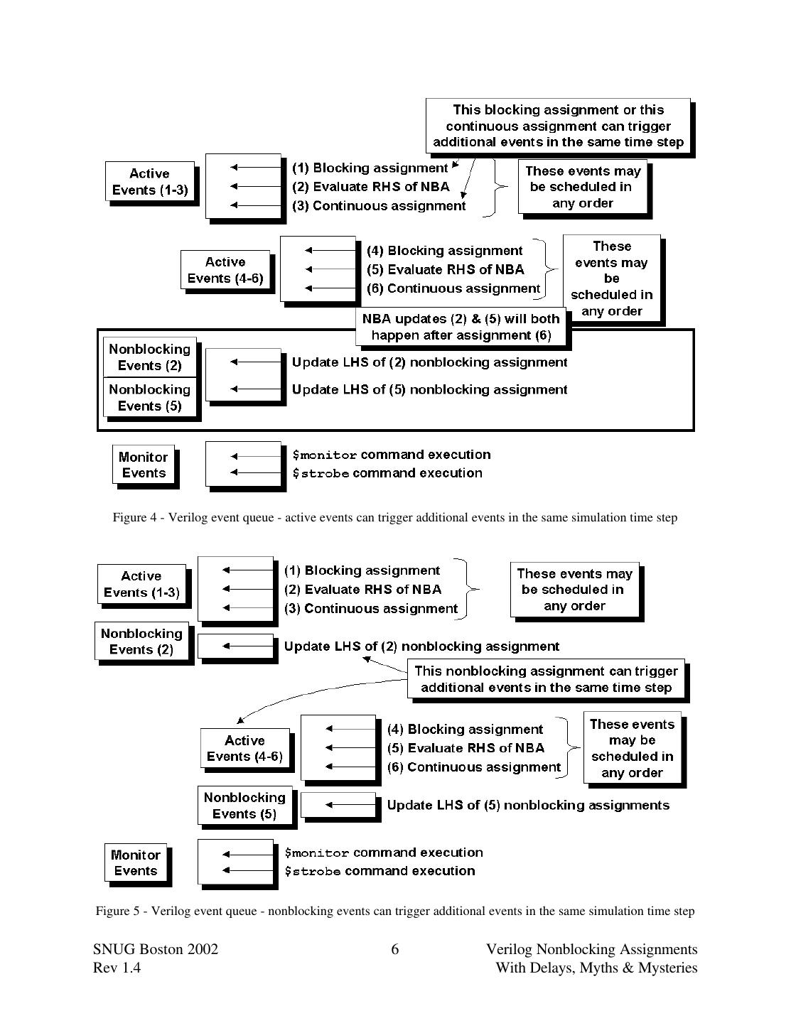
5 .2.1 Event scheduling and re-triggering As defined in section 5.3 of the IEEE 1364-1995 Verilog Standard, the "stratified event queue" is logically partitioned into four distinct queues for the current simulation time and additional queues for future simulation times. Figure 3 - The Verilog "stratified event queue" The active events queue is where most Verilog events are scheduled, including blocking assignments, continuous assignments, $display commands, evaluation of instance and primitive inputs followed by updates of primitive and instance outputs, and the evaluation of nonblocking RHS expressions. The LHS variables of nonblocking assignments are not updated in the active events queue but instead are placed in the nonblocking assign update events queue, where they remain until they are activated (moved into the active events queue). As shown in Figure 4, active events such as blocking assignments and contiuous assignments can trigger additional assignments and procedural blocks causing more active events and nonblocking assign update events to be scheduled in the same time step. Under these circumstances, the new active events would be executed before activating any of the nonblocking assign update events. As shown in Figure 5, after the nonblocking assign updates events are activated, the LHS of the nonblocking assignments are updated, which can trigger additional assignments and procedural blocks, causing more active events and nonblocking assign update events to be scheduled in the same time step. As described in the modified simulation reference model of Figure 2, simulation time does not advance while there are still active events and nonblocking assign update events to be processed in the current simulation time. SNUG Boston 2002 5 Verilog Nonblocking Assignments Rev 1.4 With Delays, Myths & Mysteries
6 . Figure 4 - Verilog event queue - active events can trigger additional events in the same simulation time step Figure 5 - Verilog event queue - nonblocking events can trigger additional events in the same simulation time step SNUG Boston 2002 6 Verilog Nonblocking Assignments Rev 1.4 With Delays, Myths & Mysteries
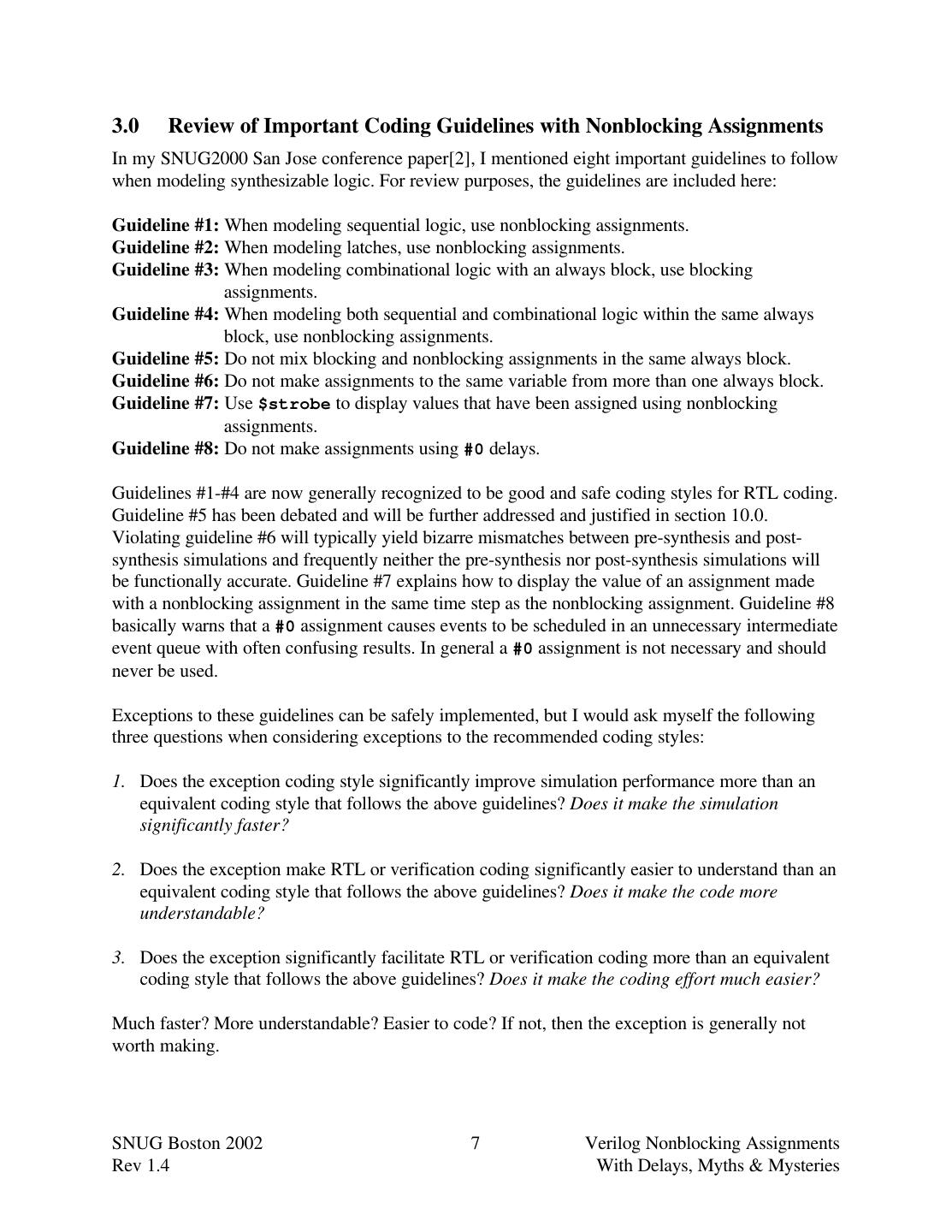
7 .3.0 Review of Important Coding Guidelines with Nonblocking Assignments In my SNUG2000 San Jose conference paper[2], I mentioned eight important guidelines to follow when modeling synthesizable logic. For review purposes, the guidelines are included here: Guideline #1: When modeling sequential logic, use nonblocking assignments. Guideline #2: When modeling latches, use nonblocking assignments. Guideline #3: When modeling combinational logic with an always block, use blocking assignments. Guideline #4: When modeling both sequential and combinational logic within the same always block, use nonblocking assignments. Guideline #5: Do not mix blocking and nonblocking assignments in the same always block. Guideline #6: Do not make assignments to the same variable from more than one always block. Guideline #7: Use $strobe to display values that have been assigned using nonblocking assignments. Guideline #8: Do not make assignments using #0 delays. Guidelines #1-#4 are now generally recognized to be good and safe coding styles for RTL coding. Guideline #5 has been debated and will be further addressed and justified in section 10.0. Violating guideline #6 will typically yield bizarre mismatches between pre-synthesis and post- synthesis simulations and frequently neither the pre-synthesis nor post-synthesis simulations will be functionally accurate. Guideline #7 explains how to display the value of an assignment made with a nonblocking assignment in the same time step as the nonblocking assignment. Guideline #8 basically warns that a #0 assignment causes events to be scheduled in an unnecessary intermediate event queue with often confusing results. In general a #0 assignment is not necessary and should never be used. Exceptions to these guidelines can be safely implemented, but I would ask myself the following three questions when considering exceptions to the recommended coding styles: 1. Does the exception coding style significantly improve simulation performance more than an equivalent coding style that follows the above guidelines? Does it make the simulation significantly faster? 2. Does the exception make RTL or verification coding significantly easier to understand than an equivalent coding style that follows the above guidelines? Does it make the code more understandable? 3. Does the exception significantly facilitate RTL or verification coding more than an equivalent coding style that follows the above guidelines? Does it make the coding effort much easier? Much faster? More understandable? Easier to code? If not, then the exception is generally not worth making. SNUG Boston 2002 7 Verilog Nonblocking Assignments Rev 1.4 With Delays, Myths & Mysteries
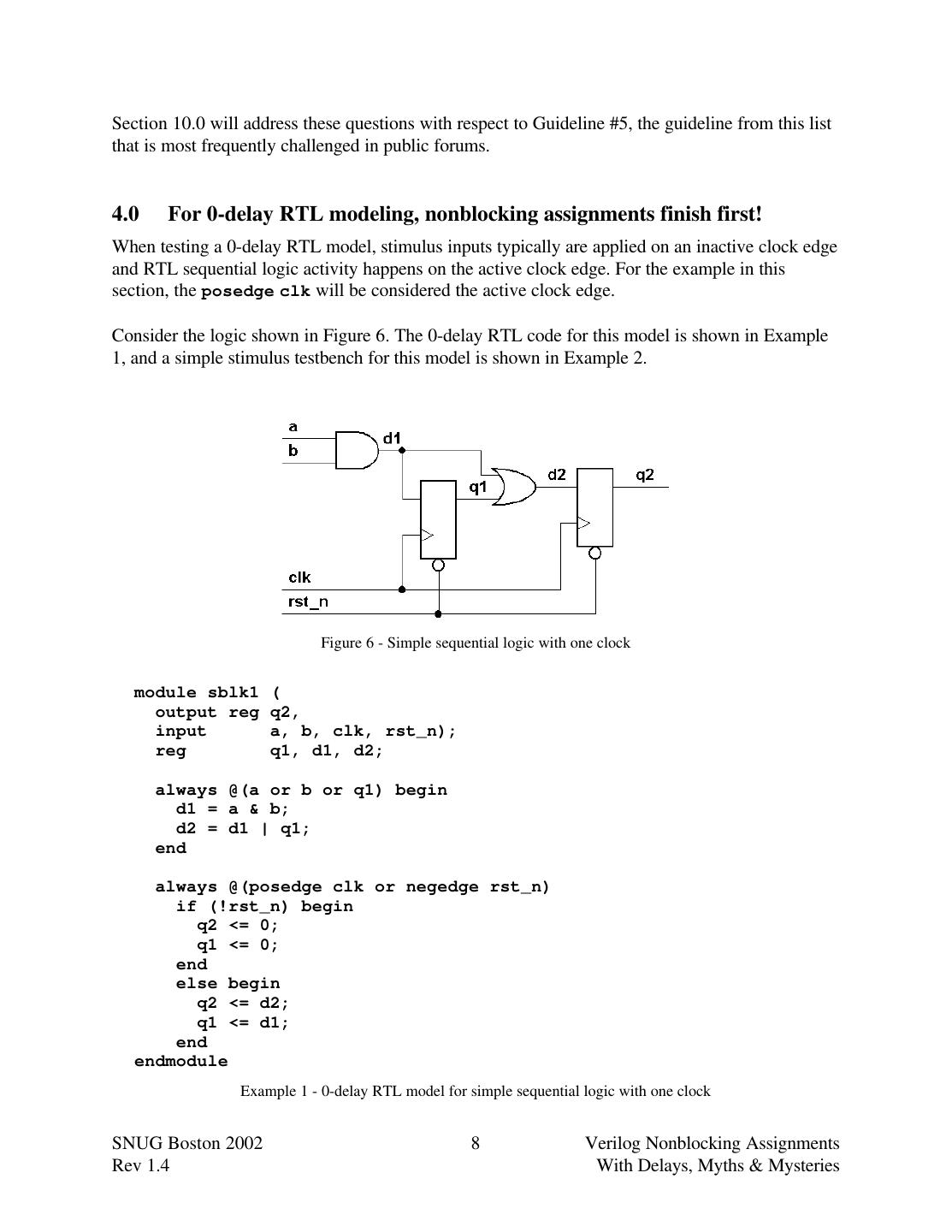
8 .Section 10.0 will address these questions with respect to Guideline #5, the guideline from this list that is most frequently challenged in public forums. 4.0 For 0-delay RTL modeling, nonblocking assignments finish first! When testing a 0-delay RTL model, stimulus inputs typically are applied on an inactive clock edge and RTL sequential logic activity happens on the active clock edge. For the example in this section, the posedge clk will be considered the active clock edge. Consider the logic shown in Figure 6. The 0-delay RTL code for this model is shown in Example 1, and a simple stimulus testbench for this model is shown in Example 2. Figure 6 - Simple sequential logic with one clock module sblk1 ( output reg q2, input a, b, clk, rst_n); reg q1, d1, d2; always @(a or b or q1) begin d1 = a & b; d2 = d1 | q1; end always @(posedge clk or negedge rst_n) if (!rst_n) begin q2 <= 0; q1 <= 0; end else begin q2 <= d2; q1 <= d1; end endmodule Example 1 - 0-delay RTL model for simple sequential logic with one clock SNUG Boston 2002 8 Verilog Nonblocking Assignments Rev 1.4 With Delays, Myths & Mysteries
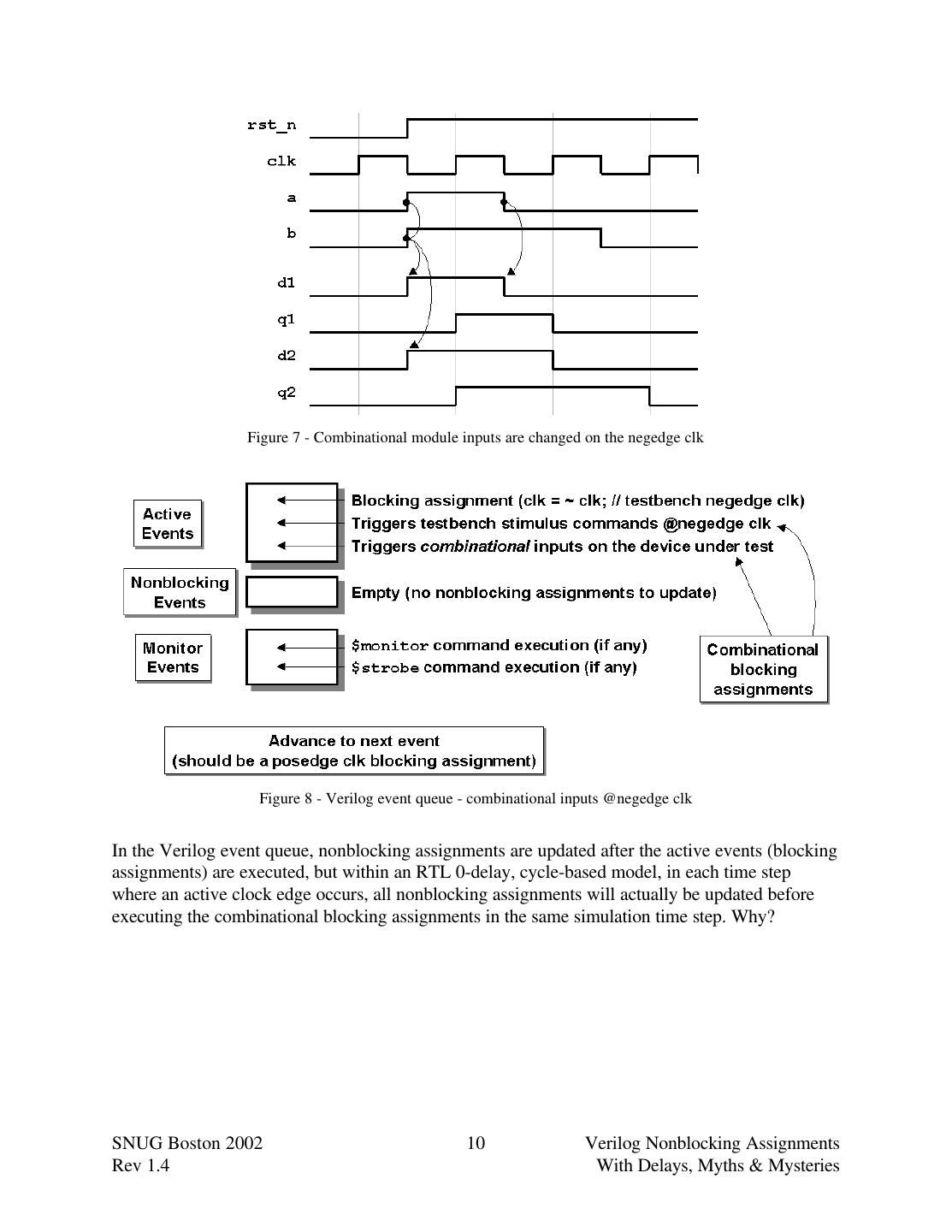
9 . module tb; reg a, b, clk, rst_n; initial begin // clock oscillator clk = 0; forever #10 clk = ~clk; end sblk1 u1 (.q2(q2), .a(a), .b(b), .clk(clk), .rst_n(rst_n)); initial begin // stimulus a = 0; b = 0; rst_n <= 0; @(posedge clk); @(negedge clk) rst_n = 1; a = 1; b = 1; @(negedge clk) a = 0; @(negedge clk) b = 0; @(negedge clk) $finish; end endmodule Example 2 - Simple testbench to apply stimulus to the 0-delay RTL model for simple sequential logic The testbench has a free-running clock oscillator with the clk initialized to 0 for the first half- cycle and the initial block sets initial values for both the a and b inputs and then resets the circuit until one cycle into the simulation (the first official negedge clk). On the first official negedge clk, the reset is removed and the primary inputs to the model, a and b, are both changed to 1's. On the next two negedge clks, first the a-input and then the b-input are successively changed to 0's. One negedge clk later the simulation is stopped with a $finish command. From this simple sequence of stimulus inputs, we can see interesting aspects of how stimulus and RTL events are scheduled in the Verilog event queue. First note that the primary inputs (a and b) and any RTL combinational logic connected to the primary inputs (d1 and d2) change on the negedge clk as shown in Figure 7. This typically means that only active events are scheduled and executed on the inactive clock edge, as shown in Figure 8. SNUG Boston 2002 9 Verilog Nonblocking Assignments Rev 1.4 With Delays, Myths & Mysteries
10 . Figure 7 - Combinational module inputs are changed on the negedge clk Figure 8 - Verilog event queue - combinational inputs @negedge clk In the Verilog event queue, nonblocking assignments are updated after the active events (blocking assignments) are executed, but within an RTL 0-delay, cycle-based model, in each time step where an active clock edge occurs, all nonblocking assignments will actually be updated before executing the combinational blocking assignments in the same simulation time step. Why? SNUG Boston 2002 10 Verilog Nonblocking Assignments Rev 1.4 With Delays, Myths & Mysteries
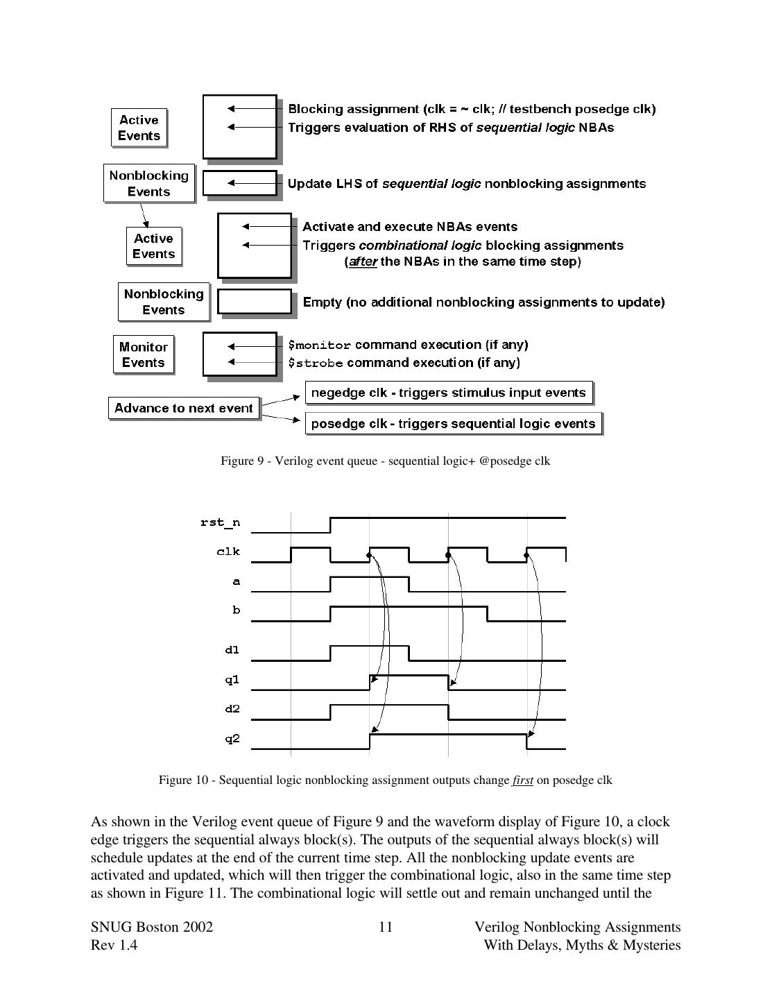
11 . Figure 9 - Verilog event queue - sequential logic+ @posedge clk Figure 10 - Sequential logic nonblocking assignment outputs change first on posedge clk As shown in the Verilog event queue of Figure 9 and the waveform display of Figure 10, a clock edge triggers the sequential always block(s). The outputs of the sequential always block(s) will schedule updates at the end of the current time step. All the nonblocking update events are activated and updated, which will then trigger the combinational logic, also in the same time step as shown in Figure 11. The combinational logic will settle out and remain unchanged until the SNUG Boston 2002 11 Verilog Nonblocking Assignments Rev 1.4 With Delays, Myths & Mysteries
12 .next posedge clk. On the next posedge clk, the sequential logic will again be updated with the stable combinational values and again trigger the combinational logic. Figure 11 - Combinational logic blocking assignment outputs change second after nonblocking assignments complete 5.0 Inertial & transport delays Inertial delay models are simulation delay models that filter pulses that are shorter than the propagation delay of Verilog gate primitives or continuous assignments. Inertial delays swallow glitches! Inertial delays are very easy for a simulator to implement because the simulator only keeps track of what the next assignment value is going to be and when it will occur. If another assignment is made to the same variable before the currently scheduled event is executed, the simulator replaces the earlier but unrealized scheduled event with the new event value and the new time when the event will occur. By default, both Verilog and VHDL simulate using inertial delays. Transport delay models are simulation delay models that pass all pulses, including pulses that are shorter than the propagation delay of corresponding Verilog procedural assignments. Transport delays pass glitches, delayed in time. The VHDL language models transport delays by adding the key word "transport" to assignments. Verilog can model RTL transport delays by adding explicit delays to the right-hand-side (RHS) of a nonblocking assignment. SNUG Boston 2002 12 Verilog Nonblocking Assignments Rev 1.4 With Delays, Myths & Mysteries
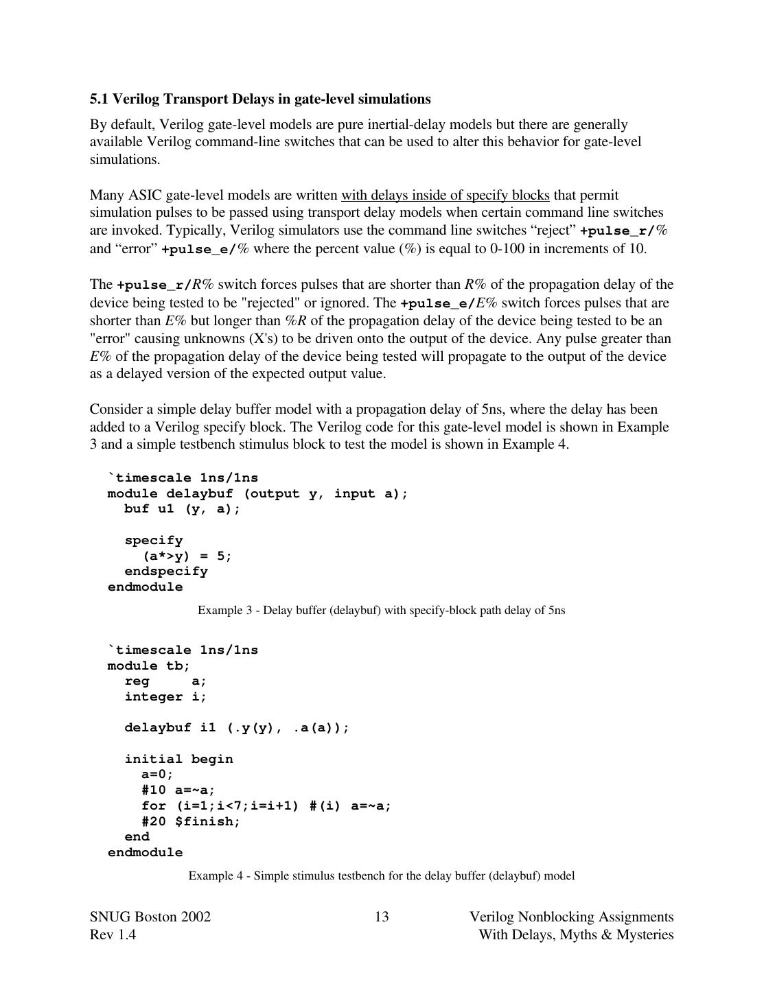
13 .5.1 Verilog Transport Delays in gate-level simulations By default, Verilog gate-level models are pure inertial-delay models but there are generally available Verilog command-line switches that can be used to alter this behavior for gate-level simulations. Many ASIC gate-level models are written with delays inside of specify blocks that permit simulation pulses to be passed using transport delay models when certain command line switches are invoked. Typically, Verilog simulators use the command line switches “reject” +pulse_r/% and “error” +pulse_e/% where the percent value (%) is equal to 0-100 in increments of 10. The +pulse_r/R% switch forces pulses that are shorter than R% of the propagation delay of the device being tested to be "rejected" or ignored. The +pulse_e/E% switch forces pulses that are shorter than E% but longer than %R of the propagation delay of the device being tested to be an "error" causing unknowns (X's) to be driven onto the output of the device. Any pulse greater than E% of the propagation delay of the device being tested will propagate to the output of the device as a delayed version of the expected output value. Consider a simple delay buffer model with a propagation delay of 5ns, where the delay has been added to a Verilog specify block. The Verilog code for this gate-level model is shown in Example 3 and a simple testbench stimulus block to test the model is shown in Example 4. `timescale 1ns/1ns module delaybuf (output y, input a); buf u1 (y, a); specify (a*>y) = 5; endspecify endmodule Example 3 - Delay buffer (delaybuf) with specify-block path delay of 5ns `timescale 1ns/1ns module tb; reg a; integer i; delaybuf i1 (.y(y), .a(a)); initial begin a=0; #10 a=~a; for (i=1;i<7;i=i+1) #(i) a=~a; #20 $finish; end endmodule Example 4 - Simple stimulus testbench for the delay buffer (delaybuf) model SNUG Boston 2002 13 Verilog Nonblocking Assignments Rev 1.4 With Delays, Myths & Mysteries
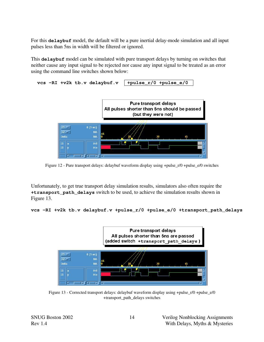
14 .For this delaybuf model, the default will be a pure inertial delay-mode simulation and all input pulses less than 5ns in width will be filtered or ignored. This delaybuf model can be simulated with pure transport delays by turning on switches that neither cause any input signal to be rejected nor cause any input signal to be treated as an error using the command line switches shown below: vcs -RI +v2k tb.v delaybuf.v +pulse_r/0 +pulse_e/0 Figure 12 - Pure transport delays: delaybuf waveform display using +pulse_r/0 +pulse_e/0 switches Unfortunately, to get true transport delay simulation results, simulators also often require the +transport_path_delays switch to be used, to achieve the simulation results shown in Figure 13. vcs -RI +v2k tb.v delaybuf.v +pulse_r/0 +pulse_e/0 +transport_path_delays Figure 13 - Corrected transport delays: delaybuf waveform display using +pulse_r/0 +pulse_e/0 +transport_path_delays switches SNUG Boston 2002 14 Verilog Nonblocking Assignments Rev 1.4 With Delays, Myths & Mysteries
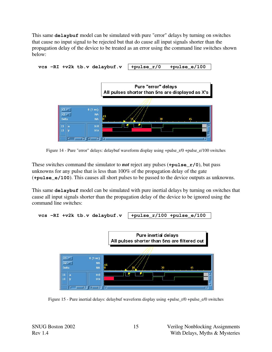
15 .This same delaybuf model can be simulated with pure "error" delays by turning on switches that cause no input signal to be rejected but that do cause all input signals shorter than the propagation delay of the device to be treated as an error using the command line switches shown below: vcs -RI +v2k tb.v delaybuf.v +pulse_r/0 +pulse_e/100 Figure 14 - Pure "error" delays: delaybuf waveform display using +pulse_r/0 +pulse_e/100 switches These switches command the simulator to not reject any pulses (+pulse_r/0), but pass unknowns for any pulse that is less than 100% of the propagation delay of the gate (+pulse_e/100). This causes all short pulses to be passed to the device outputs as unknowns. This same delaybuf model can be simulated with pure inertial delays by turning on switches that cause all input signals shorter than the propagation delay of the device to be ignored using the command line switches: vcs -RI +v2k tb.v delaybuf.v +pulse_r/100 +pulse_e/100 Figure 15 - Pure inertial delays: delaybuf waveform display using +pulse_r/0 +pulse_e/0 switches SNUG Boston 2002 15 Verilog Nonblocking Assignments Rev 1.4 With Delays, Myths & Mysteries
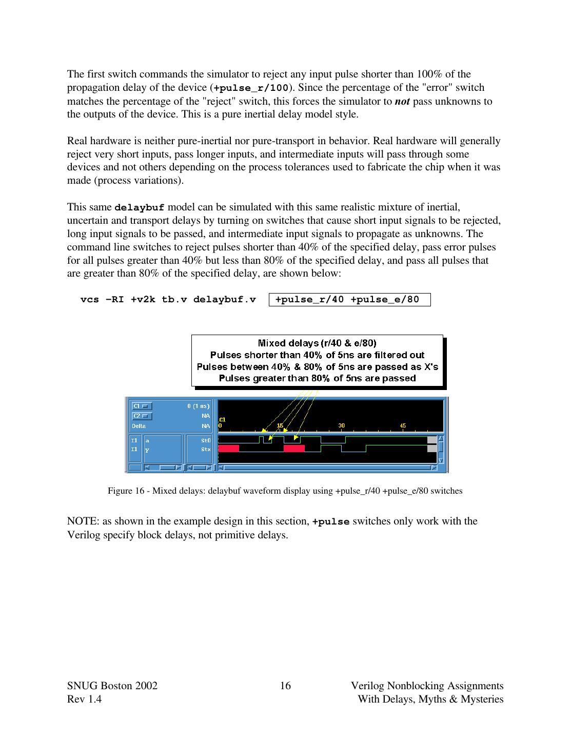
16 .The first switch commands the simulator to reject any input pulse shorter than 100% of the propagation delay of the device (+pulse_r/100). Since the percentage of the "error" switch matches the percentage of the "reject" switch, this forces the simulator to not pass unknowns to the outputs of the device. This is a pure inertial delay model style. Real hardware is neither pure-inertial nor pure-transport in behavior. Real hardware will generally reject very short inputs, pass longer inputs, and intermediate inputs will pass through some devices and not others depending on the process tolerances used to fabricate the chip when it was made (process variations). This same delaybuf model can be simulated with this same realistic mixture of inertial, uncertain and transport delays by turning on switches that cause short input signals to be rejected, long input signals to be passed, and intermediate input signals to propagate as unknowns. The command line switches to reject pulses shorter than 40% of the specified delay, pass error pulses for all pulses greater than 40% but less than 80% of the specified delay, and pass all pulses that are greater than 80% of the specified delay, are shown below: vcs -RI +v2k tb.v delaybuf.v +pulse_r/40 +pulse_e/80 Figure 16 - Mixed delays: delaybuf waveform display using +pulse_r/40 +pulse_e/80 switches NOTE: as shown in the example design in this section, +pulse switches only work with the Verilog specify block delays, not primitive delays. SNUG Boston 2002 16 Verilog Nonblocking Assignments Rev 1.4 With Delays, Myths & Mysteries
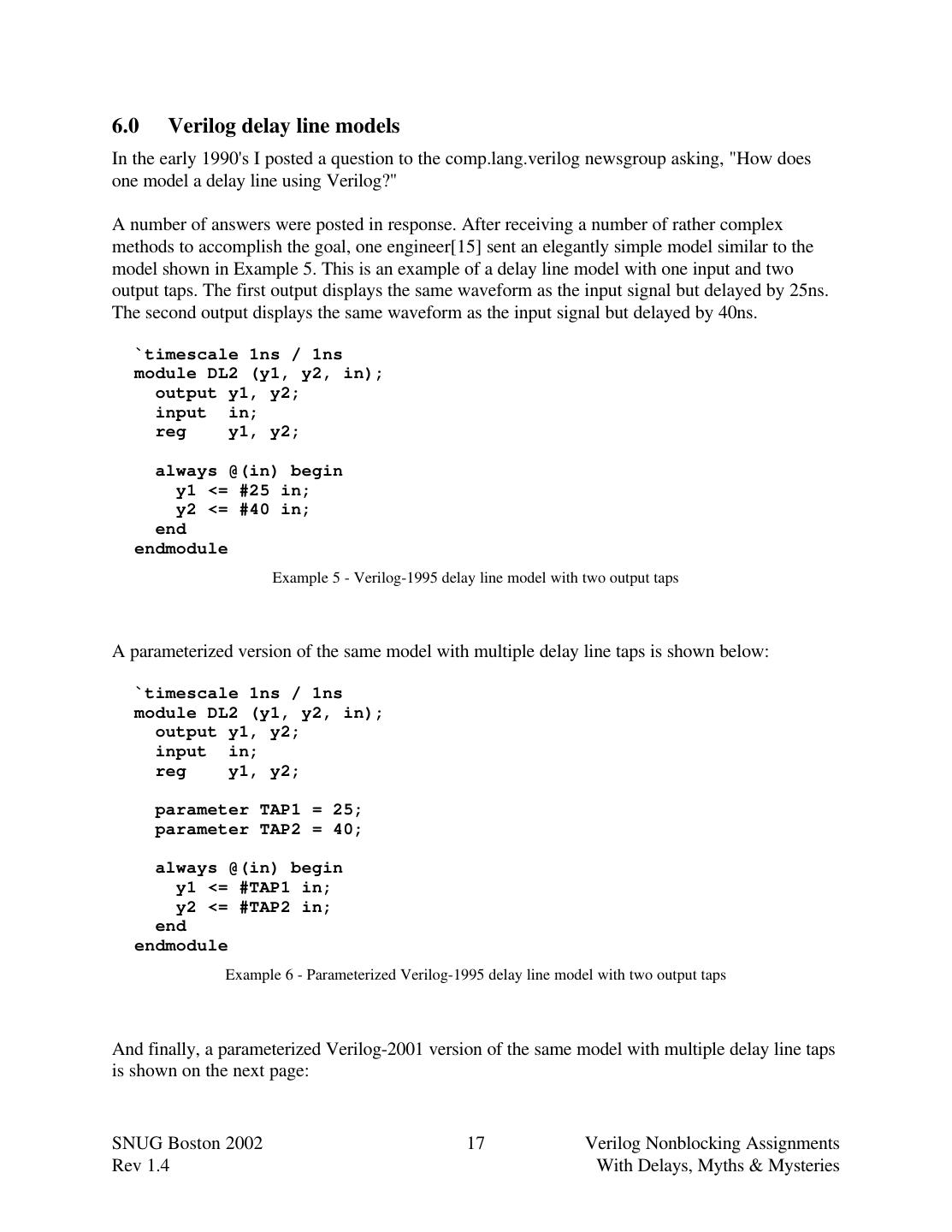
17 .6.0 Verilog delay line models In the early 1990's I posted a question to the comp.lang.verilog newsgroup asking, "How does one model a delay line using Verilog?" A number of answers were posted in response. After receiving a number of rather complex methods to accomplish the goal, one engineer[15] sent an elegantly simple model similar to the model shown in Example 5. This is an example of a delay line model with one input and two output taps. The first output displays the same waveform as the input signal but delayed by 25ns. The second output displays the same waveform as the input signal but delayed by 40ns. `timescale 1ns / 1ns module DL2 (y1, y2, in); output y1, y2; input in; reg y1, y2; always @(in) begin y1 <= #25 in; y2 <= #40 in; end endmodule Example 5 - Verilog-1995 delay line model with two output taps A parameterized version of the same model with multiple delay line taps is shown below: `timescale 1ns / 1ns module DL2 (y1, y2, in); output y1, y2; input in; reg y1, y2; parameter TAP1 = 25; parameter TAP2 = 40; always @(in) begin y1 <= #TAP1 in; y2 <= #TAP2 in; end endmodule Example 6 - Parameterized Verilog-1995 delay line model with two output taps And finally, a parameterized Verilog-2001 version of the same model with multiple delay line taps is shown on the next page: SNUG Boston 2002 17 Verilog Nonblocking Assignments Rev 1.4 With Delays, Myths & Mysteries
18 . `timescale 1ns / 1ns module DL2 #(parameter TAP1 = 25, TAP2 = 40) (output reg y1, y2, input in); always @(in) begin y1 <= #TAP1 in; y2 <= #TAP2 in; end endmodule Example 7 - Parameterized Verilog-2001 delay line model with two output taps Since Verilog delays are ignored by synthesis tools, what do delay lines have to do with synthesis? Delays may be important to mixed RTL and gate simulations. More on this subject is discussed in section 11.0. An important guideline that should be noted in every Verilog book (but often is missing) and taught in every beginning Verilog class (but often is not), is that whenever an engineer adds a #delay to a module, the module should be preceded by a `timescale directive; otherwise, the delays in the module are at the mercy of the last `timescale directive declared, which may not match the desired timing of the current module being compiled. Compiler directives, such as the `timescale directive, are compile-order dependent. Guideline: Add a `timescale directive in front of every module that contains #delays. 7.0 The #1 delay To delay or not to delay, that is the question! Myth: #1 delays are required to fix problems with nonblocking assignments. I have worked with many engineers at many companies and have often seen engineers add #1 to the RHS of all nonblocking assignments. When I ask engineers why they have added delays to their nonblocking assignments, frequently the answer given is "Verilog nonblocking assignments are broken and adding #1 fixes the problem!" Truth: Nonblocking assignments are not broken. The engineer's understanding is broken! There are a few good reasons and many bad reasons to add #1 to the RHS of nonblocking assignments. Some of these reasons include: Good reason #1: Adding #1 to nonblocking assignments will cause an output change to be delayed by 1 time unit. This often eases the debugging task when using a waveform viewer. Consider the register models in Example 8 and Example 9. SNUG Boston 2002 18 Verilog Nonblocking Assignments Rev 1.4 With Delays, Myths & Mysteries
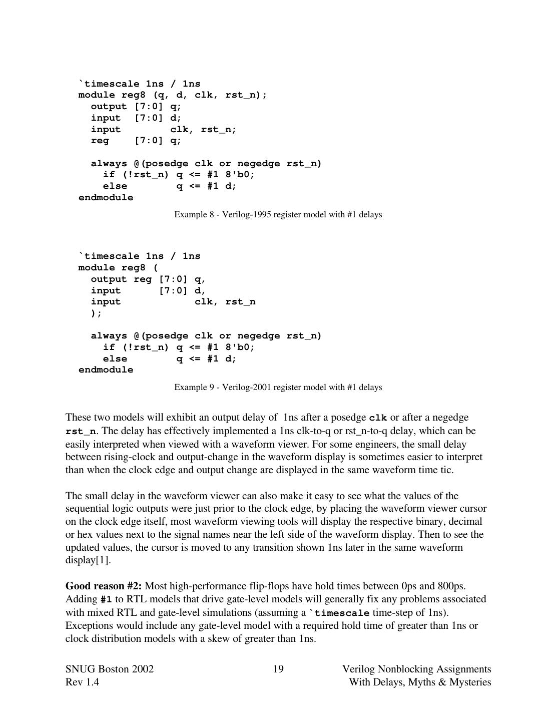
19 . `timescale 1ns / 1ns module reg8 (q, d, clk, rst_n); output [7:0] q; input [7:0] d; input clk, rst_n; reg [7:0] q; always @(posedge clk or negedge rst_n) if (!rst_n) q <= #1 8'b0; else q <= #1 d; endmodule Example 8 - Verilog-1995 register model with #1 delays `timescale 1ns / 1ns module reg8 ( output reg [7:0] q, input [7:0] d, input clk, rst_n ); always @(posedge clk or negedge rst_n) if (!rst_n) q <= #1 8'b0; else q <= #1 d; endmodule Example 9 - Verilog-2001 register model with #1 delays These two models will exhibit an output delay of 1ns after a posedge clk or after a negedge rst_n. The delay has effectively implemented a 1ns clk-to-q or rst_n-to-q delay, which can be easily interpreted when viewed with a waveform viewer. For some engineers, the small delay between rising-clock and output-change in the waveform display is sometimes easier to interpret than when the clock edge and output change are displayed in the same waveform time tic. The small delay in the waveform viewer can also make it easy to see what the values of the sequential logic outputs were just prior to the clock edge, by placing the waveform viewer cursor on the clock edge itself, most waveform viewing tools will display the respective binary, decimal or hex values next to the signal names near the left side of the waveform display. Then to see the updated values, the cursor is moved to any transition shown 1ns later in the same waveform display[1]. Good reason #2: Most high-performance flip-flops have hold times between 0ps and 800ps. Adding #1 to RTL models that drive gate-level models will generally fix any problems associated with mixed RTL and gate-level simulations (assuming a `timescale time-step of 1ns). Exceptions would include any gate-level model with a required hold time of greater than 1ns or clock distribution models with a skew of greater than 1ns. SNUG Boston 2002 19 Verilog Nonblocking Assignments Rev 1.4 With Delays, Myths & Mysteries
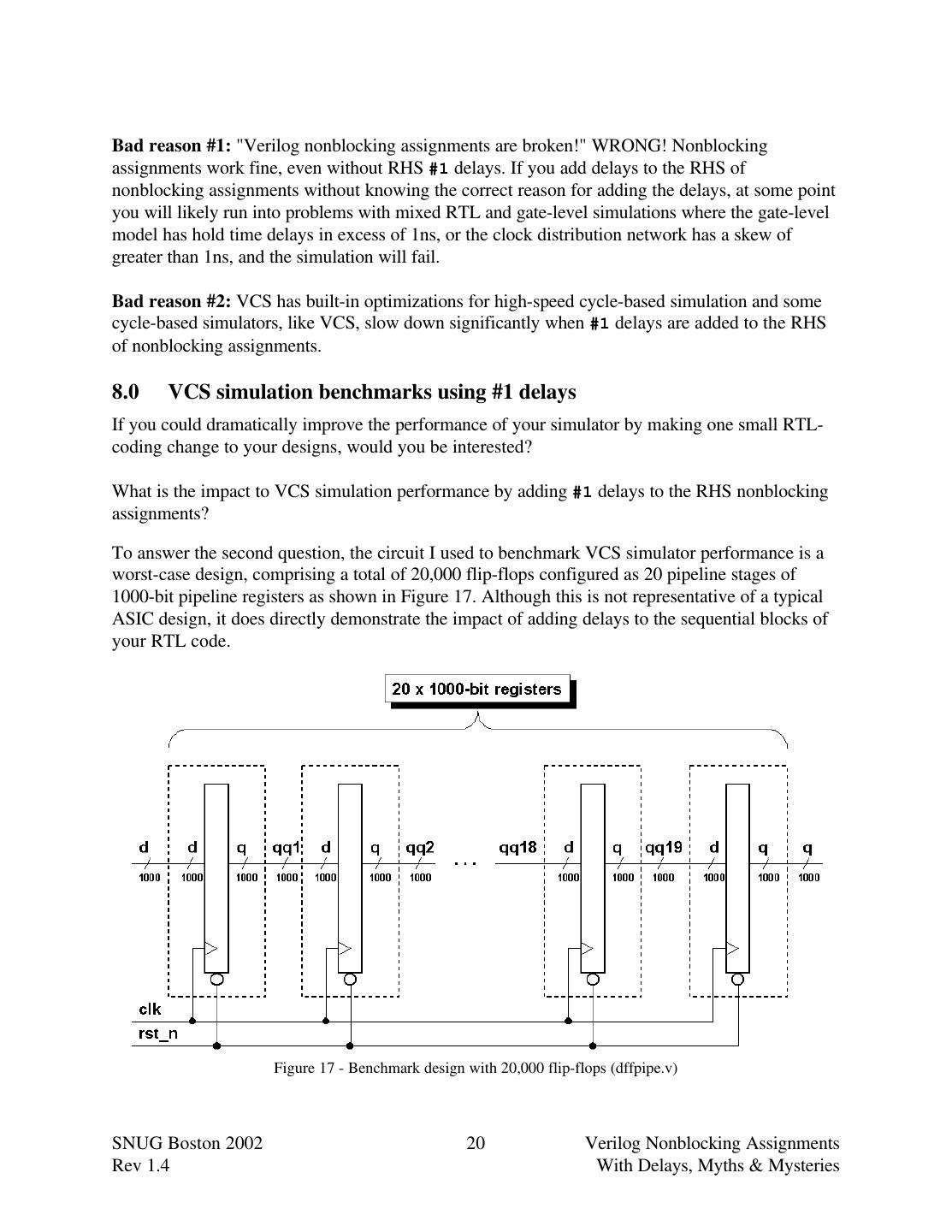
20 .Bad reason #1: "Verilog nonblocking assignments are broken!" WRONG! Nonblocking assignments work fine, even without RHS #1 delays. If you add delays to the RHS of nonblocking assignments without knowing the correct reason for adding the delays, at some point you will likely run into problems with mixed RTL and gate-level simulations where the gate-level model has hold time delays in excess of 1ns, or the clock distribution network has a skew of greater than 1ns, and the simulation will fail. Bad reason #2: VCS has built-in optimizations for high-speed cycle-based simulation and some cycle-based simulators, like VCS, slow down significantly when #1 delays are added to the RHS of nonblocking assignments. 8.0 VCS simulation benchmarks using #1 delays If you could dramatically improve the performance of your simulator by making one small RTL- coding change to your designs, would you be interested? What is the impact to VCS simulation performance by adding #1 delays to the RHS nonblocking assignments? To answer the second question, the circuit I used to benchmark VCS simulator performance is a worst-case design, comprising a total of 20,000 flip-flops configured as 20 pipeline stages of 1000-bit pipeline registers as shown in Figure 17. Although this is not representative of a typical ASIC design, it does directly demonstrate the impact of adding delays to the sequential blocks of your RTL code. Figure 17 - Benchmark design with 20,000 flip-flops (dffpipe.v) SNUG Boston 2002 20 Verilog Nonblocking Assignments Rev 1.4 With Delays, Myths & Mysteries
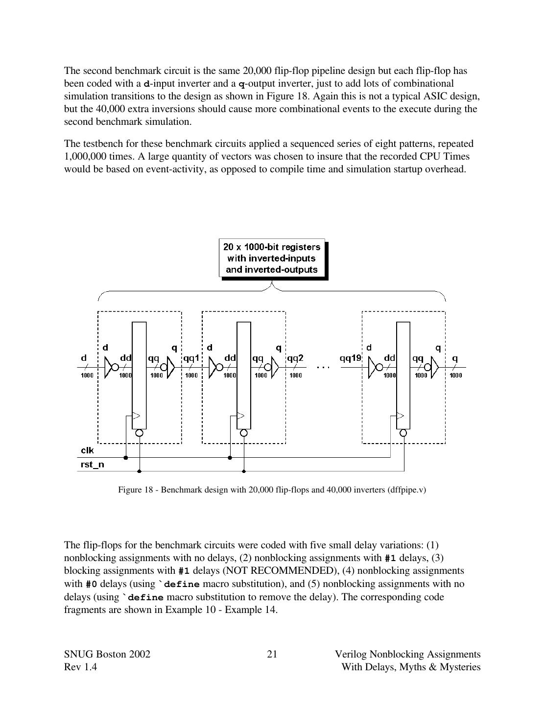
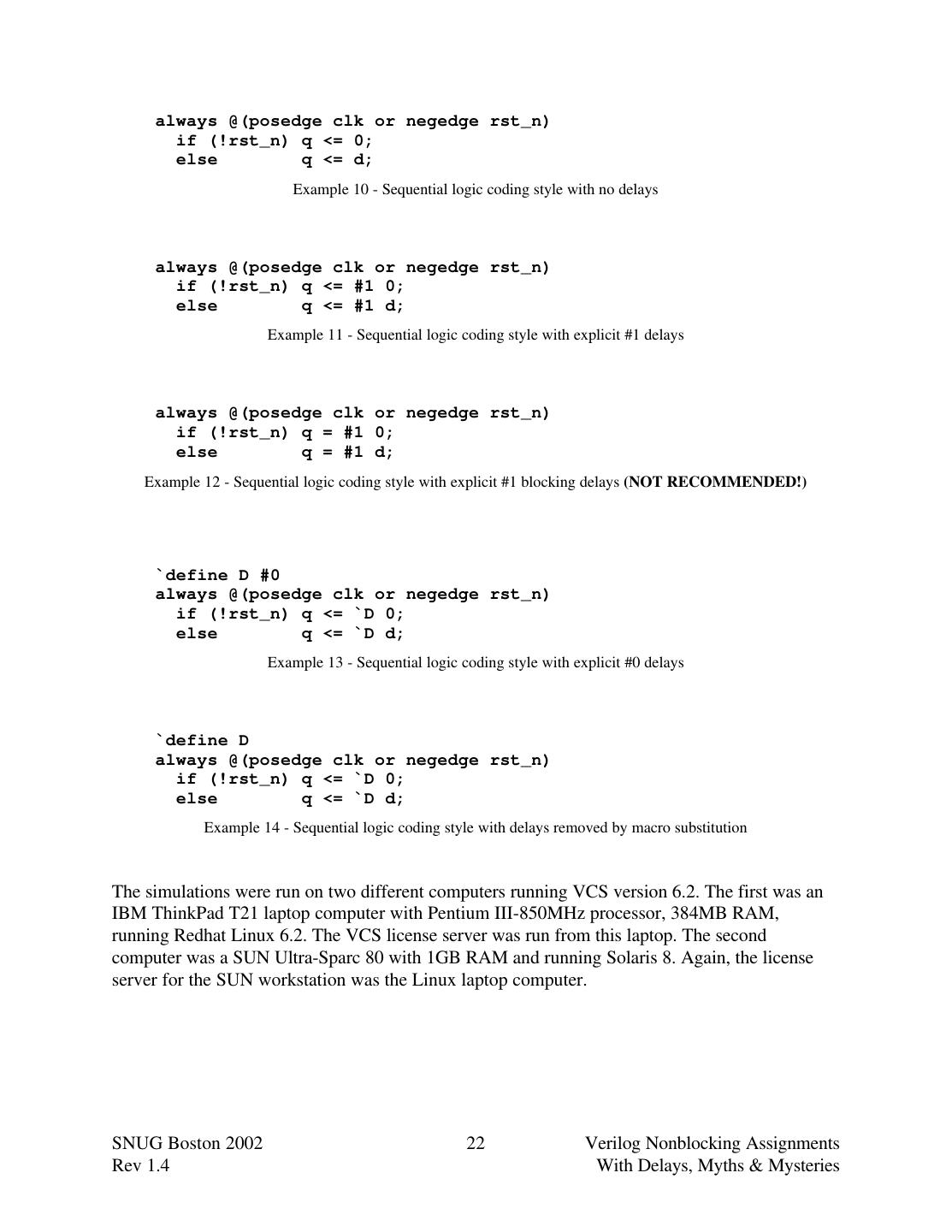
21 .The second benchmark circuit is the same 20,000 flip-flop pipeline design but each flip-flop has been coded with a d-input inverter and a q-output inverter, just to add lots of combinational simulation transitions to the design as shown in Figure 18. Again this is not a typical ASIC design, but the 40,000 extra inversions should cause more combinational events to the execute during the second benchmark simulation. The testbench for these benchmark circuits applied a sequenced series of eight patterns, repeated 1,000,000 times. A large quantity of vectors was chosen to insure that the recorded CPU Times would be based on event-activity, as opposed to compile time and simulation startup overhead. Figure 18 - Benchmark design with 20,000 flip-flops and 40,000 inverters (dffpipe.v) The flip-flops for the benchmark circuits were coded with five small delay variations: (1) nonblocking assignments with no delays, (2) nonblocking assignments with #1 delays, (3) blocking assignments with #1 delays (NOT RECOMMENDED), (4) nonblocking assignments with #0 delays (using `define macro substitution), and (5) nonblocking assignments with no delays (using `define macro substitution to remove the delay). The corresponding code fragments are shown in Example 10 - Example 14. SNUG Boston 2002 21 Verilog Nonblocking Assignments Rev 1.4 With Delays, Myths & Mysteries
22 . always @(posedge clk or negedge rst_n) if (!rst_n) q <= 0; else q <= d; Example 10 - Sequential logic coding style with no delays always @(posedge clk or negedge rst_n) if (!rst_n) q <= #1 0; else q <= #1 d; Example 11 - Sequential logic coding style with explicit #1 delays always @(posedge clk or negedge rst_n) if (!rst_n) q = #1 0; else q = #1 d; Example 12 - Sequential logic coding style with explicit #1 blocking delays (NOT RECOMMENDED!) `define D #0 always @(posedge clk or negedge rst_n) if (!rst_n) q <= `D 0; else q <= `D d; Example 13 - Sequential logic coding style with explicit #0 delays `define D always @(posedge clk or negedge rst_n) if (!rst_n) q <= `D 0; else q <= `D d; Example 14 - Sequential logic coding style with delays removed by macro substitution The simulations were run on two different computers running VCS version 6.2. The first was an IBM ThinkPad T21 laptop computer with Pentium III-850MHz processor, 384MB RAM, running Redhat Linux 6.2. The VCS license server was run from this laptop. The second computer was a SUN Ultra-Sparc 80 with 1GB RAM and running Solaris 8. Again, the license server for the SUN workstation was the Linux laptop computer. SNUG Boston 2002 22 Verilog Nonblocking Assignments Rev 1.4 With Delays, Myths & Mysteries
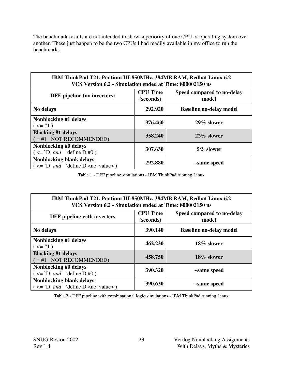
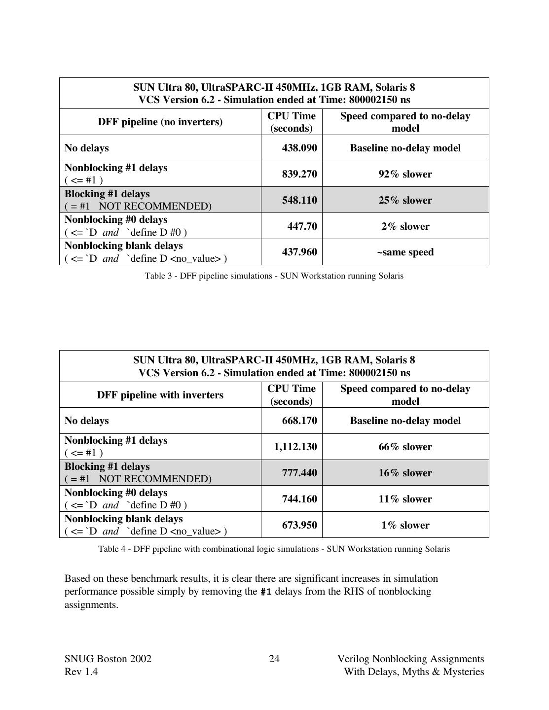
23 .The benchmark results are not intended to show superiority of one CPU or operating system over another. These just happen to be the two CPUs I had readily available in my office to run the benchmarks. IBM ThinkPad T21, Pentium III-850MHz, 384MB RAM, Redhat Linux 6.2 VCS Version 6.2 - Simulation ended at Time: 800002150 ns CPU Time Speed compared to no-delay DFF pipeline (no inverters) (seconds) model No delays 292.920 Baseline no-delay model Nonblocking #1 delays 376.460 29% slower ( <= #1 ) Blocking #1 delays 358.240 22% slower ( = #1 NOT RECOMMENDED) Nonblocking #0 delays 307.630 5% slower ( <= `D and `define D #0 ) Nonblocking blank delays 292.880 ~same speed ( <= `D and `define D <no_value> ) Table 1 - DFF pipeline simulations - IBM ThinkPad running Linux IBM ThinkPad T21, Pentium III-850MHz, 384MB RAM, Redhat Linux 6.2 VCS Version 6.2 - Simulation ended at Time: 800002150 ns CPU Time Speed compared to no-delay DFF pipeline with inverters (seconds) model No delays 390.140 Baseline no-delay model Nonblocking #1 delays 462.230 18% slower ( <= #1 ) Blocking #1 delays 458.750 18% slower ( = #1 NOT RECOMMENDED) Nonblocking #0 delays 390.320 ~same speed ( <= `D and `define D #0 ) Nonblocking blank delays 390.630 ~same speed ( <= `D and `define D <no_value> ) Table 2 - DFF pipeline with combinational logic simulations - IBM ThinkPad running Linux SNUG Boston 2002 23 Verilog Nonblocking Assignments Rev 1.4 With Delays, Myths & Mysteries
24 . SUN Ultra 80, UltraSPARC-II 450MHz, 1GB RAM, Solaris 8 VCS Version 6.2 - Simulation ended at Time: 800002150 ns CPU Time Speed compared to no-delay DFF pipeline (no inverters) (seconds) model No delays 438.090 Baseline no-delay model Nonblocking #1 delays 839.270 92% slower ( <= #1 ) Blocking #1 delays 548.110 25% slower ( = #1 NOT RECOMMENDED) Nonblocking #0 delays 447.70 2% slower ( <= `D and `define D #0 ) Nonblocking blank delays 437.960 ~same speed ( <= `D and `define D <no_value> ) Table 3 - DFF pipeline simulations - SUN Workstation running Solaris SUN Ultra 80, UltraSPARC-II 450MHz, 1GB RAM, Solaris 8 VCS Version 6.2 - Simulation ended at Time: 800002150 ns CPU Time Speed compared to no-delay DFF pipeline with inverters (seconds) model No delays 668.170 Baseline no-delay model Nonblocking #1 delays 1,112.130 66% slower ( <= #1 ) Blocking #1 delays 777.440 16% slower ( = #1 NOT RECOMMENDED) Nonblocking #0 delays 744.160 11% slower ( <= `D and `define D #0 ) Nonblocking blank delays 673.950 1% slower ( <= `D and `define D <no_value> ) Table 4 - DFF pipeline with combinational logic simulations - SUN Workstation running Solaris Based on these benchmark results, it is clear there are significant increases in simulation performance possible simply by removing the #1 delays from the RHS of nonblocking assignments. SNUG Boston 2002 24 Verilog Nonblocking Assignments Rev 1.4 With Delays, Myths & Mysteries
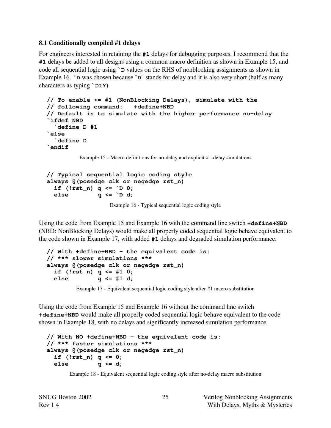
25 .8.1 Conditionally compiled #1 delays For engineers interested in retaining the #1 delays for debugging purposes, I recommend that the #1 delays be added to all designs using a common macro definition as shown in Example 15, and code all sequential logic using `D values on the RHS of nonblocking assignments as shown in Example 16. `D was chosen because "D" stands for delay and it is also very short (half as many characters as typing `DLY). // To enable <= #1 (NonBlocking Delays), simulate with the // following command: +define+NBD // Default is to simulate with the higher performance no-delay `ifdef NBD `define D #1 `else `define D `endif Example 15 - Macro definitions for no-delay and explicit #1-delay simulations // Typical sequential logic coding style always @(posedge clk or negedge rst_n) if (!rst_n) q <= `D 0; else q <= `D d; Example 16 - Typical sequential logic coding style Using the code from Example 15 and Example 16 with the command line switch +define+NBD (NBD: NonBlocking Delays) would make all properly coded sequential logic behave equivalent to the code shown in Example 17, with added #1 delays and degraded simulation performance. // With +define+NBD - the equivalent code is: // *** slower simulations *** always @(posedge clk or negedge rst_n) if (!rst_n) q <= #1 0; else q <= #1 d; Example 17 - Equivalent sequential logic coding style after #1 macro substitution Using the code from Example 15 and Example 16 without the command line switch +define+NBD would make all properly coded sequential logic behave equivalent to the code shown in Example 18, with no delays and significantly increased simulation performance. // With NO +define+NBD - the equivalent code is: // *** faster simulations *** always @(posedge clk or negedge rst_n) if (!rst_n) q <= 0; else q <= d; Example 18 - Equivalent sequential logic coding style after no-delay macro substitution SNUG Boston 2002 25 Verilog Nonblocking Assignments Rev 1.4 With Delays, Myths & Mysteries
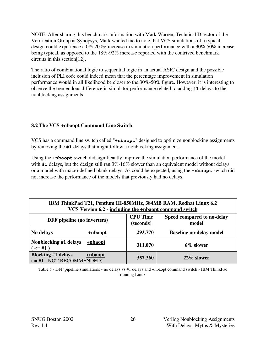
26 .NOTE: After sharing this benchmark information with Mark Warren, Technical Director of the Verification Group at Synopsys, Mark wanted me to note that VCS simulations of a typical design could experience a 0%-200% increase in simulation performance with a 30%-50% increase being typical, as opposed to the 18%-92% increase reported with the contrived benchmark circuits in this section[12]. The ratio of combinational logic to sequential logic in an actual ASIC design and the possible inclusion of PLI code could indeed mean that the percentage improvement in simulation performance would in all likelihood be closer to the 30%-50% figure. However, it is interesting to observe the tremendous difference in simulator performance related to adding #1 delays to the nonblocking assignments. 8.2 The VCS +nbaopt Command Line Switch VCS has a command line switch called "+nbaopt" designed to optimize nonblocking assignments by removing the #1 delays that might follow a nonblocking assignment. Using the +nbaopt switch did significantly improve the simulation performance of the model with #1 delays, but the design still ran 3%-16% slower than an equivalent model without delays or a model with macro-defined blank delays. As could be expected, using the +nbaopt switch did not increase the performance of the models that previously had no delays. IBM ThinkPad T21, Pentium III-850MHz, 384MB RAM, Redhat Linux 6.2 VCS Version 6.2 - including the +nbaopt command switch CPU Time Speed compared to no-delay DFF pipeline (no inverters) (seconds) model No delays +nbaopt 293.770 Baseline no-delay model Nonblocking #1 delays +nbaopt 311.070 6% slower ( <= #1 ) Blocking #1 delays +nbaopt 357.360 22% slower ( = #1 NOT RECOMMENDED) Table 5 - DFF pipeline simulations - no delays vs #1 delays and +nbaopt command switch - IBM ThinkPad running Linux SNUG Boston 2002 26 Verilog Nonblocking Assignments Rev 1.4 With Delays, Myths & Mysteries
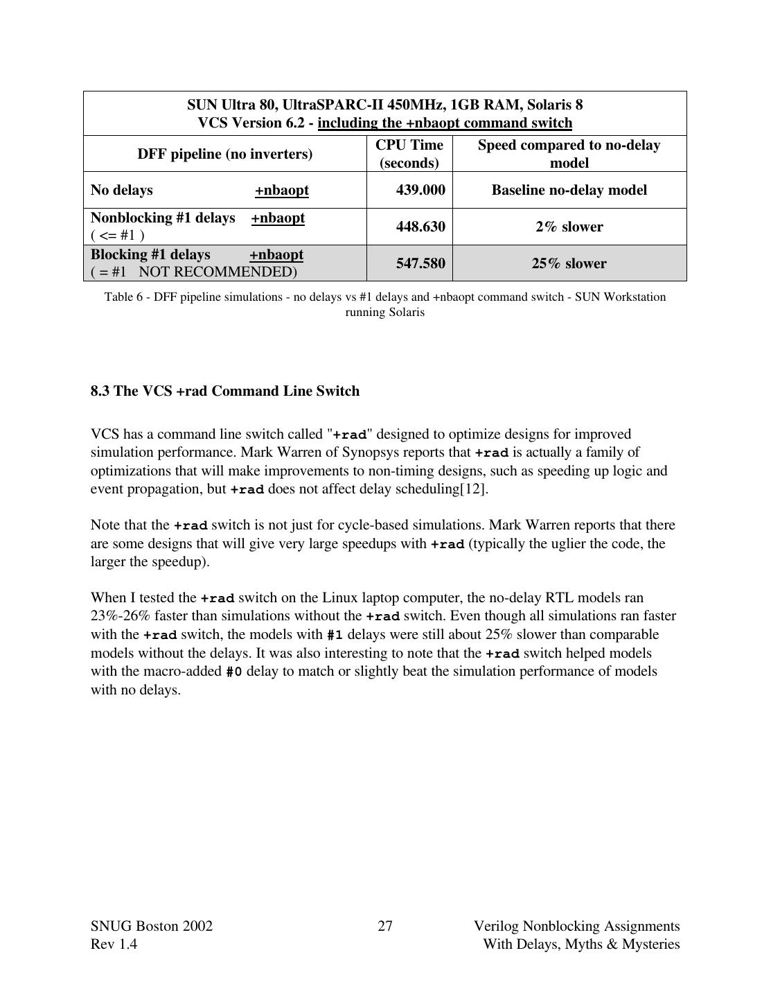
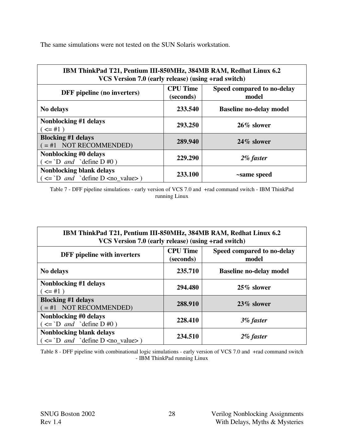
27 . SUN Ultra 80, UltraSPARC-II 450MHz, 1GB RAM, Solaris 8 VCS Version 6.2 - including the +nbaopt command switch CPU Time Speed compared to no-delay DFF pipeline (no inverters) (seconds) model No delays +nbaopt 439.000 Baseline no-delay model Nonblocking #1 delays +nbaopt 448.630 2% slower ( <= #1 ) Blocking #1 delays +nbaopt 547.580 25% slower ( = #1 NOT RECOMMENDED) Table 6 - DFF pipeline simulations - no delays vs #1 delays and +nbaopt command switch - SUN Workstation running Solaris 8.3 The VCS +rad Command Line Switch VCS has a command line switch called "+rad" designed to optimize designs for improved simulation performance. Mark Warren of Synopsys reports that +rad is actually a family of optimizations that will make improvements to non-timing designs, such as speeding up logic and event propagation, but +rad does not affect delay scheduling[12]. Note that the +rad switch is not just for cycle-based simulations. Mark Warren reports that there are some designs that will give very large speedups with +rad (typically the uglier the code, the larger the speedup). When I tested the +rad switch on the Linux laptop computer, the no-delay RTL models ran 23%-26% faster than simulations without the +rad switch. Even though all simulations ran faster with the +rad switch, the models with #1 delays were still about 25% slower than comparable models without the delays. It was also interesting to note that the +rad switch helped models with the macro-added #0 delay to match or slightly beat the simulation performance of models with no delays. SNUG Boston 2002 27 Verilog Nonblocking Assignments Rev 1.4 With Delays, Myths & Mysteries
28 .The same simulations were not tested on the SUN Solaris workstation. IBM ThinkPad T21, Pentium III-850MHz, 384MB RAM, Redhat Linux 6.2 VCS Version 7.0 (early release) (using +rad switch) CPU Time Speed compared to no-delay DFF pipeline (no inverters) (seconds) model No delays 233.540 Baseline no-delay model Nonblocking #1 delays 293.250 26% slower ( <= #1 ) Blocking #1 delays 289.940 24% slower ( = #1 NOT RECOMMENDED) Nonblocking #0 delays 229.290 2% faster ( <= `D and `define D #0 ) Nonblocking blank delays 233.100 ~same speed ( <= `D and `define D <no_value> ) Table 7 - DFF pipeline simulations - early version of VCS 7.0 and +rad command switch - IBM ThinkPad running Linux IBM ThinkPad T21, Pentium III-850MHz, 384MB RAM, Redhat Linux 6.2 VCS Version 7.0 (early release) (using +rad switch) CPU Time Speed compared to no-delay DFF pipeline with inverters (seconds) model No delays 235.710 Baseline no-delay model Nonblocking #1 delays 294.480 25% slower ( <= #1 ) Blocking #1 delays 288.910 23% slower ( = #1 NOT RECOMMENDED) Nonblocking #0 delays 228.410 3% faster ( <= `D and `define D #0 ) Nonblocking blank delays 234.510 2% faster ( <= `D and `define D <no_value> ) Table 8 - DFF pipeline with combinational logic simulations - early version of VCS 7.0 and +rad command switch - IBM ThinkPad running Linux SNUG Boston 2002 28 Verilog Nonblocking Assignments Rev 1.4 With Delays, Myths & Mysteries
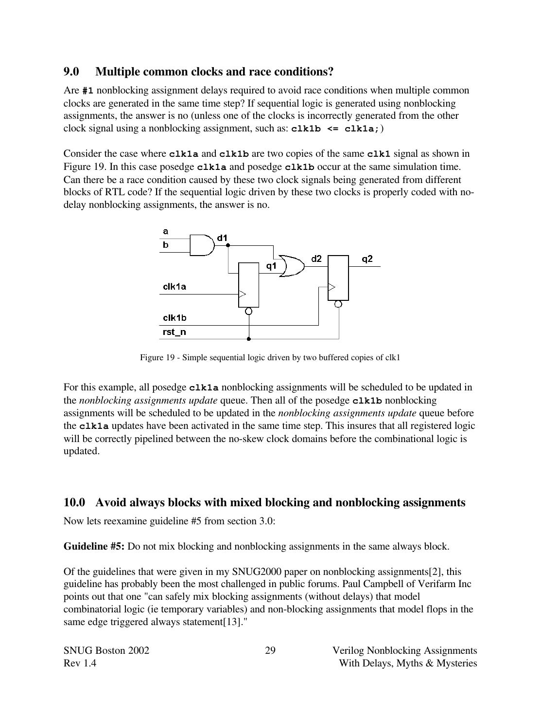
29 .9.0 Multiple common clocks and race conditions? Are #1 nonblocking assignment delays required to avoid race conditions when multiple common clocks are generated in the same time step? If sequential logic is generated using nonblocking assignments, the answer is no (unless one of the clocks is incorrectly generated from the other clock signal using a nonblocking assignment, such as: clk1b <= clk1a;) Consider the case where clk1a and clk1b are two copies of the same clk1 signal as shown in Figure 19. In this case posedge clk1a and posedge clk1b occur at the same simulation time. Can there be a race condition caused by these two clock signals being generated from different blocks of RTL code? If the sequential logic driven by these two clocks is properly coded with no- delay nonblocking assignments, the answer is no. Figure 19 - Simple sequential logic driven by two buffered copies of clk1 For this example, all posedge clk1a nonblocking assignments will be scheduled to be updated in the nonblocking assignments update queue. Then all of the posedge clk1b nonblocking assignments will be scheduled to be updated in the nonblocking assignments update queue before the clk1a updates have been activated in the same time step. This insures that all registered logic will be correctly pipelined between the no-skew clock domains before the combinational logic is updated. 10.0 Avoid always blocks with mixed blocking and nonblocking assignments Now lets reexamine guideline #5 from section 3.0: Guideline #5: Do not mix blocking and nonblocking assignments in the same always block. Of the guidelines that were given in my SNUG2000 paper on nonblocking assignments[2], this guideline has probably been the most challenged in public forums. Paul Campbell of Verifarm Inc points out that one "can safely mix blocking assignments (without delays) that model combinatorial logic (ie temporary variables) and non-blocking assignments that model flops in the same edge triggered always statement[13]." SNUG Boston 2002 29 Verilog Nonblocking Assignments Rev 1.4 With Delays, Myths & Mysteries


