- 快召唤伙伴们来围观吧
- 微博 QQ QQ空间 贴吧
- 文档嵌入链接
- 复制
- 微信扫一扫分享
- 已成功复制到剪贴板
Two-Level Scheduling (Con’t) Device Driverses
展开查看详情
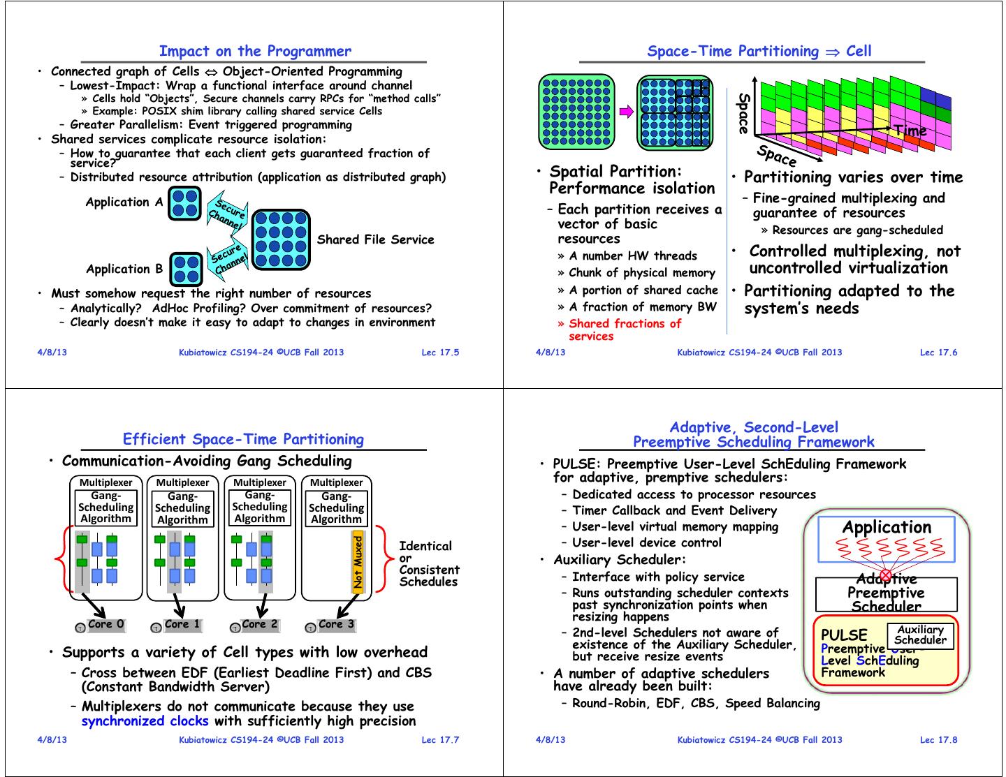
1 . Goals for Today CS194-24 • Tessellation (finished) Advanced Operating Systems • Devices and Device Drivers Structures and Implementation Lecture 19 Two-Level Scheduling (Con’t) Interactive is important! Device Drivers Ask Questions! April 9th, 2014 Prof. John Kubiatowicz http://inst.eecs.berkeley.edu/~cs194-24 Note: Some slides and/or pictures in the following are adapted from slides ©2013 4/8/13 Kubiatowicz CS194-24 ©UCB Fall 2013 Lec 17.2 Recall: the Cell Applications are Interconnected Graphs of Services • Properties of a Cell – A user-level software component with guaranteed resources – Has full control over resources it owns (“Bare Metal”) Device Secure Real-Time Drivers – Contains at least one memory protection domain (possibly more) Channel Cells Secure – Contains a set of secured channel endpoints to other Cells (Audio, Channel Secure – Hardware-enforced security context to protect the privacy of Video) Channel Parallel information and decrypt information (a Hardware TCB) Core Application Library File Service • Each Cell schedules its resources exclusively with application- • Component-based model of computation specific user-level schedulers – Applications consist of interacting components – Gang-scheduled hardware thread resources (“Harts”) – Explicitly asynchronous/non-blocking – Virtual Memory mapping and paging – Components may be local or remote – Storage and Communication resources • Communication defines Security Model » Cache partitions, memory bandwidth, power – Channels are points at which data may be compromised – Use of Guaranteed fractions of system services – Channels define points for QoS constraints • Predictability of Behavior • Naming (Brokering) process for initiating endpoints – Ability to model performance vs resources – Need to find compatible remote services – Ability for user-level schedulers to better provide QoS – Continuous adaptation: links changing over time! 4/8/13 Kubiatowicz CS194-24 ©UCB Fall 2013 Lec 17.3 4/8/13 Kubiatowicz CS194-24 ©UCB Fall 2013 Lec 17.4
2 . Impact on the Programmer Space-Time Partitioning Cell • Connected graph of Cells Object-Oriented Programming – Lowest-Impact: Wrap a functional interface around channel » Cells hold “Objects”, Secure channels carry RPCs for “method calls” Space » Example: POSIX shim library calling shared service Cells – Greater Parallelism: Event triggered programming Time • Shared services complicate resource isolation: – How to guarantee that each client gets guaranteed fraction of service? – Distributed resource attribution (application as distributed graph) • Spatial Partition: • Partitioning varies over time Performance isolation Application A – Fine-grained multiplexing and – Each partition receives a guarantee of resources vector of basic » Resources are gang-scheduled Shared File Service resources » A number HW threads • Controlled multiplexing, not Application B » Chunk of physical memory uncontrolled virtualization • Must somehow request the right number of resources » A portion of shared cache • Partitioning adapted to the – Analytically? AdHoc Profiling? Over commitment of resources? » A fraction of memory BW system’s needs – Clearly doesn’t make it easy to adapt to changes in environment » Shared fractions of services 4/8/13 Kubiatowicz CS194-24 ©UCB Fall 2013 Lec 17.5 4/8/13 Kubiatowicz CS194-24 ©UCB Fall 2013 Lec 17.6 Adaptive, Second-Level Efficient Space-Time Partitioning Preemptive Scheduling Framework • Communication-Avoiding Gang Scheduling • PULSE: Preemptive User-Level SchEduling Framework Multiplexer Multiplexer Multiplexer Multiplexer for adaptive, premptive schedulers: Gang‐ Gang‐ Gang‐ Gang‐ – Dedicated access to processor resources Scheduling Scheduling Scheduling Scheduling – Timer Callback and Event Delivery Algorithm Algorithm Application Algorithm Algorithm – User-level virtual memory mapping – User-level device control Not Muxed Identical or • Auxiliary Scheduler: Consistent Schedules – Interface with policy service Adaptive – Runs outstanding scheduler contexts Preemptive past synchronization points when Scheduler resizing happens Core 0 Core 1 Core 2 Core 3 Auxiliary – 2nd-level Schedulers not aware of PULSE existence of the Auxiliary Scheduler, Scheduler • Supports a variety of Cell types with low overhead Preemptive User- but receive resize events Level SchEduling – Cross between EDF (Earliest Deadline First) and CBS • A number of adaptive schedulers Framework (Constant Bandwidth Server) have already been built: – Multiplexers do not communicate because they use – Round-Robin, EDF, CBS, Speed Balancing synchronized clocks with sufficiently high precision 4/8/13 Kubiatowicz CS194-24 ©UCB Fall 2013 Lec 17.7 4/8/13 Kubiatowicz CS194-24 ©UCB Fall 2013 Lec 17.8
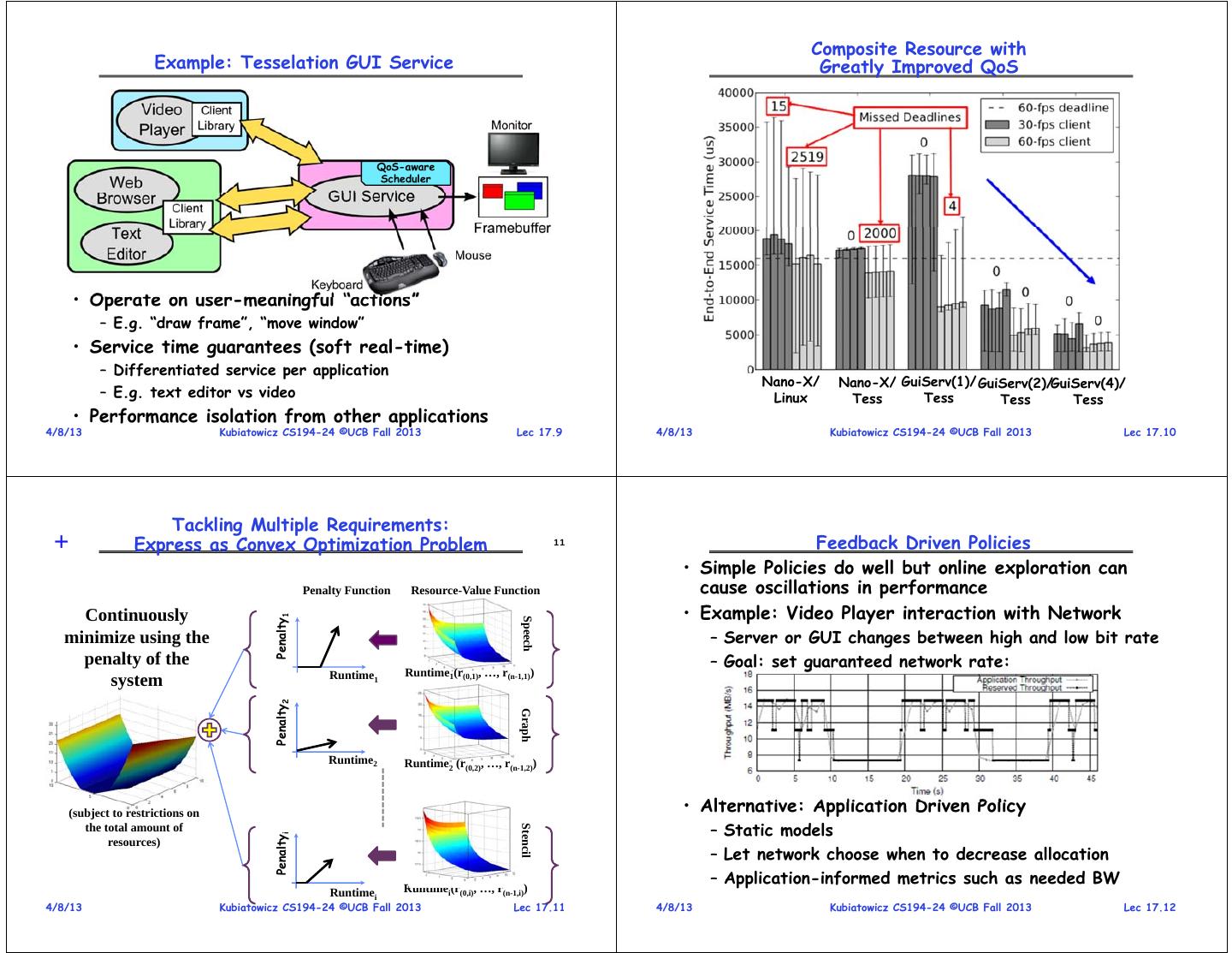
3 . Composite Resource with Example: Tesselation GUI Service Greatly Improved QoS QoS-aware Scheduler • Operate on user-meaningful “actions” – E.g. “draw frame”, “move window” • Service time guarantees (soft real-time) – Differentiated service per application Nano-X/ Nano-X/ GuiServ(1)/ GuiServ(2)/GuiServ(4)/ – E.g. text editor vs video Linux Tess Tess Tess Tess • Performance isolation from other applications 4/8/13 Kubiatowicz CS194-24 ©UCB Fall 2013 Lec 17.9 4/8/13 Kubiatowicz CS194-24 ©UCB Fall 2013 Lec 17.10 Tackling Multiple Requirements: + Express as Convex Optimization Problem 11 Feedback Driven Policies • Simple Policies do well but online exploration can Penalty Function Resource-Value Function cause oscillations in performance Continuously • Example: Video Player interaction with Network Penalty1 Speech minimize using the – Server or GUI changes between high and low bit rate penalty of the – Goal: set guaranteed network rate: Runtime1 Runtime1(r(0,1), …, r(n-1,1)) system Penalty2 Graph Runtime2 Runtime2 (r(0,2), …, r(n-1,2)) (subject to restrictions on • Alternative: Application Driven Policy – Static models Stencil the total amount of Penaltyi resources) – Let network choose when to decrease allocation – Application-informed metrics such as needed BW Runtimei Runtimei(r(0,i), …, r(n-1,i)) 4/8/13 Kubiatowicz CS194-24 ©UCB Fall 2013 Lec 17.11 4/8/13 Kubiatowicz CS194-24 ©UCB Fall 2013 Lec 17.12
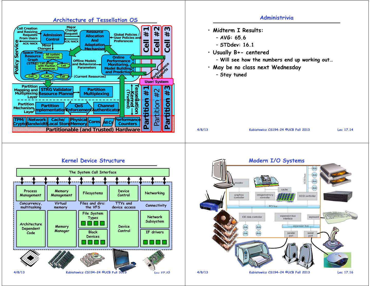
4 . Architecture of Tessellation OS Administrivia Major Cell Creation • Midterm I Results: Cell #2 Cell #1 Cell #3 and Resizing Change Resource Request Global Policies / Requests Admission Allocation From Users Control And User Policies and – AVG: 65.6 ACK/NACK Preferences Policy Service ACK/NACK Minor Adaptation – STDdev: 16.1 Changes Mechanism Space-Time All system • Usually B+- centered Resource resources Online Graph Offline Models Performance – Will see how the numbers end up working out… (STRG) Cell group and Behavioral Monitoring, with fraction of resources Cell Parameters Model Building, • May be no class next Wednesday and Prediction Cell Cell Cell (Current Resources) – Stay tuned User/System Partition Tessellation Partition #1 Partition #3 Mapping and STRG Validator Partition Partition #2 (Trusted) Kernel Multiplexing Resource Planner Multiplexing Layer Partition Partition QoS Channel Mechanism Layer ImplementationEnforcement Authenticator TPM/ Network Cache/ Physical Performance Cores NICs CryptoBandwidthLocal Store Memory Counters 4/8/13 Partitionable (and Kubiatowicz Trusted) CS194-24 Hardware ©UCB Fall 2013 Lec 17.13 4/8/13 Kubiatowicz CS194-24 ©UCB Fall 2013 Lec 17.14 Kernel Device Structure Modern I/O Systems The System Call Interface Process Memory Device Filesystems Networking Management Management Control Concurrency, Virtual Files and dirs: TTYs and Connectivity multitasking memory the VFS device access File System Types Network Subsystem Architecture Memory Device Dependent Manager Block Control IF drivers Code Devices 4/8/13 Kubiatowicz CS194-24 ©UCB Fall 2013 Lec 17.15 4/8/13 Kubiatowicz CS194-24 ©UCB Fall 2013 Lec 17.16
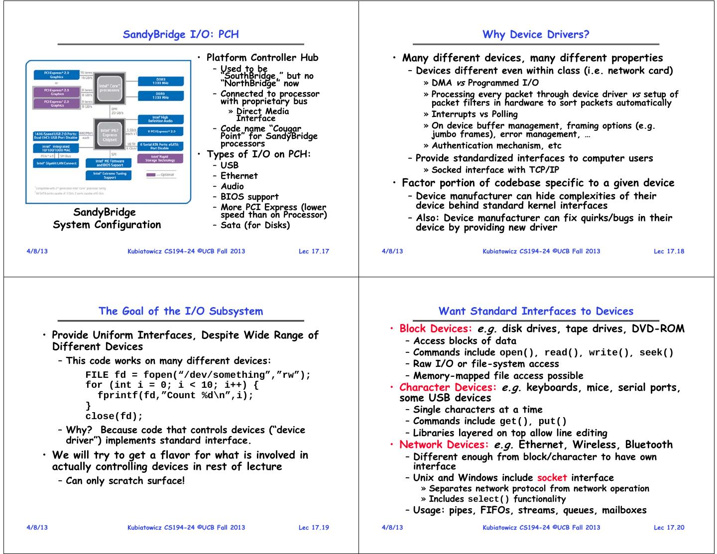
5 . SandyBridge I/O: PCH Why Device Drivers? • Platform Controller Hub • Many different devices, many different properties – Used to be – Devices different even within class (i.e. network card) “SouthBridge,” but no “NorthBridge” now » DMA vs Programmed I/O – Connected to processor » Processing every packet through device driver vs setup of with proprietary bus packet filters in hardware to sort packets automatically » Direct Media » Interrupts vs Polling Interface – Code name “Cougar » On device buffer management, framing options (e.g. Point” for SandyBridge jumbo frames), error management, … processors » Authentication mechanism, etc • Types of I/O on PCH: – Provide standardized interfaces to computer users – USB » Socked interface with TCP/IP – Ethernet – Audio • Factor portion of codebase specific to a given device – BIOS support – Device manufacturer can hide complexities of their – More PCI Express (lower device behind standard kernel interfaces SandyBridge speed than on Processor) – Also: Device manufacturer can fix quirks/bugs in their System Configuration – Sata (for Disks) device by providing new driver 4/8/13 Kubiatowicz CS194-24 ©UCB Fall 2013 Lec 17.17 4/8/13 Kubiatowicz CS194-24 ©UCB Fall 2013 Lec 17.18 The Goal of the I/O Subsystem Want Standard Interfaces to Devices • Block Devices: e.g. disk drives, tape drives, DVD-ROM • Provide Uniform Interfaces, Despite Wide Range of – Access blocks of data Different Devices – Commands include open(), read(), write(), seek() – This code works on many different devices: – Raw I/O or file-system access FILE fd = fopen(“/dev/something”,”rw”); – Memory-mapped file access possible for (int i = 0; i < 10; i++) { • Character Devices: e.g. keyboards, mice, serial ports, fprintf(fd,”Count %d\n”,i); some USB devices } – Single characters at a time close(fd); – Commands include get(), put() – Why? Because code that controls devices (“device – Libraries layered on top allow line editing driver”) implements standard interface. • Network Devices: e.g. Ethernet, Wireless, Bluetooth • We will try to get a flavor for what is involved in – Different enough from block/character to have own actually controlling devices in rest of lecture interface – Can only scratch surface! – Unix and Windows include socket interface » Separates network protocol from network operation » Includes select() functionality – Usage: pipes, FIFOs, streams, queues, mailboxes 4/8/13 Kubiatowicz CS194-24 ©UCB Fall 2013 Lec 17.19 4/8/13 Kubiatowicz CS194-24 ©UCB Fall 2013 Lec 17.20
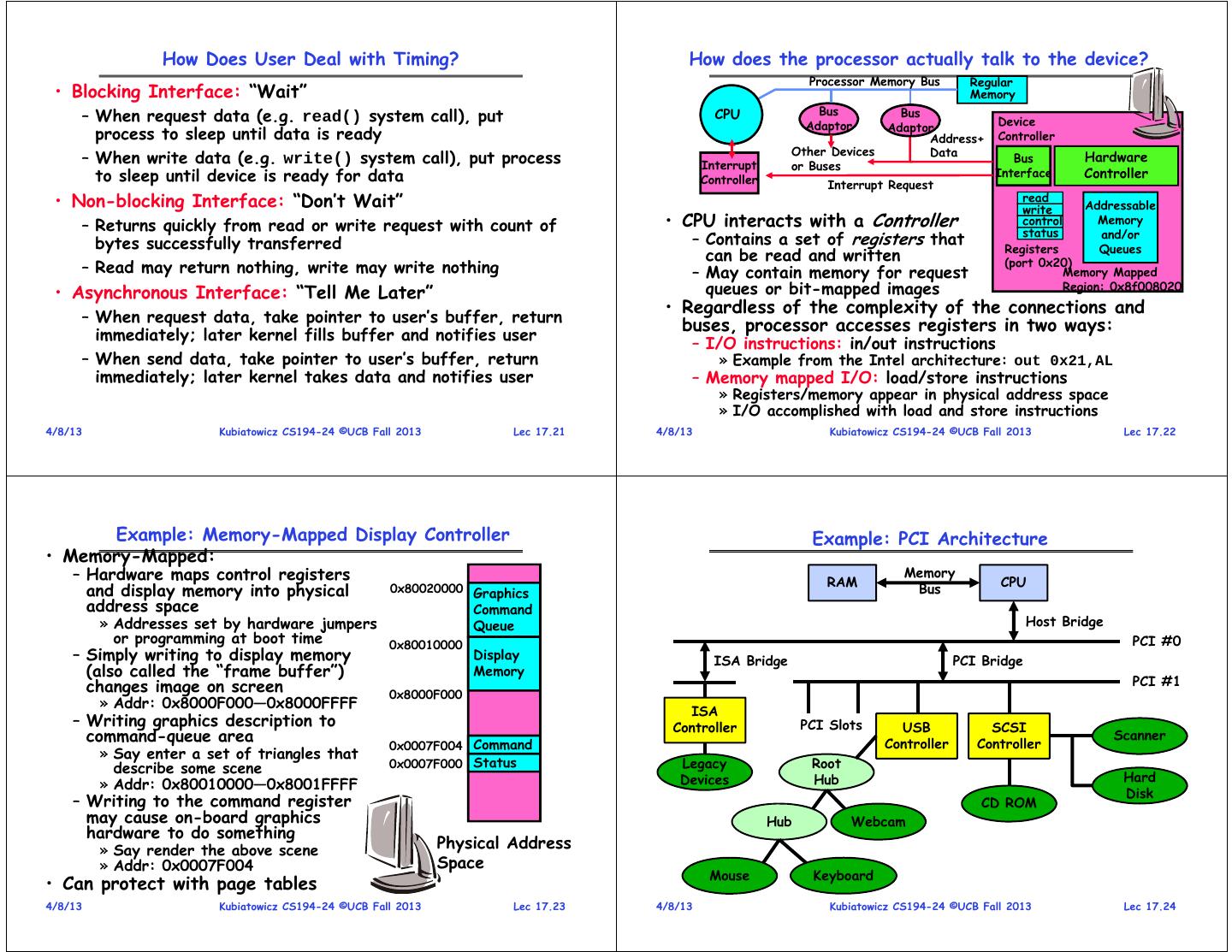
6 . How Does User Deal with Timing? How does the processor actually talk to the device? Processor Memory Bus Regular • Blocking Interface: “Wait” Memory Bus – When request data (e.g. read() system call), put CPU Bus Device Adaptor Adaptor process to sleep until data is ready Address+ Controller Other Devices Data – When write data (e.g. write() system call), put process Interrupt or Buses Bus Hardware to sleep until device is ready for data Controller Interrupt Request Interface Controller • Non-blocking Interface: “Don’t Wait” read write Addressable – Returns quickly from read or write request with count of • CPU interacts with a Controller control Memory status and/or bytes successfully transferred – Contains a set of registers that Registers Queues can be read and written (port 0x20) – Read may return nothing, write may write nothing – May contain memory for request Memory Mapped • Asynchronous Interface: “Tell Me Later” queues or bit-mapped images Region: 0x8f008020 • Regardless of the complexity of the connections and – When request data, take pointer to user’s buffer, return buses, processor accesses registers in two ways: immediately; later kernel fills buffer and notifies user – I/O instructions: in/out instructions – When send data, take pointer to user’s buffer, return » Example from the Intel architecture: out 0x21,AL immediately; later kernel takes data and notifies user – Memory mapped I/O: load/store instructions » Registers/memory appear in physical address space » I/O accomplished with load and store instructions 4/8/13 Kubiatowicz CS194-24 ©UCB Fall 2013 Lec 17.21 4/8/13 Kubiatowicz CS194-24 ©UCB Fall 2013 Lec 17.22 Example: Memory-Mapped Display Controller Example: PCI Architecture • Memory-Mapped: – Hardware maps control registers RAM Memory CPU and display memory into physical 0x80020000 Graphics Bus address space Command » Addresses set by hardware jumpers Queue Host Bridge or programming at boot time 0x80010000 PCI #0 – Simply writing to display memory Display ISA Bridge PCI Bridge (also called the “frame buffer”) Memory changes image on screen PCI #1 0x8000F000 » Addr: 0x8000F000—0x8000FFFF ISA – Writing graphics description to Controller PCI Slots USB SCSI command-queue area Controller Controller Scanner 0x0007F004 Command » Say enter a set of triangles that describe some scene 0x0007F000 Status Legacy Root Devices Hub Hard » Addr: 0x80010000—0x8001FFFF Disk – Writing to the command register CD ROM may cause on-board graphics Hub Webcam hardware to do something » Say render the above scene Physical Address » Addr: 0x0007F004 Space Mouse Keyboard • Can protect with page tables 4/8/13 Kubiatowicz CS194-24 ©UCB Fall 2013 Lec 17.23 4/8/13 Kubiatowicz CS194-24 ©UCB Fall 2013 Lec 17.24
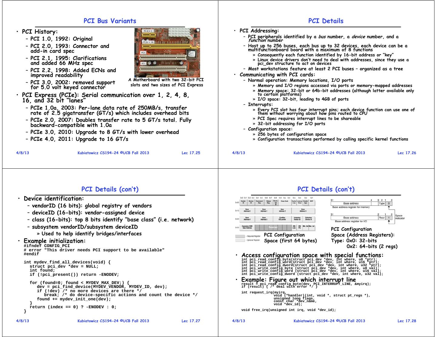
7 . PCI Bus Variants PCI Details • PCI History: • PCI Addressing: – PCI peripherals identified by a bus number, a device number, and a – PCI 1.0, 1992: Original function number – PCI 2.0, 1993: Connector and – Host up to 256 buses, each bus up to 32 devices, each device can be a add-in card spec multifunctionboard board with a maximum of 8 functions » Consequently each function identified by 16-bit address or “key” – PCI 2.1, 1995: Clarifications » Linux device drivers don’t need to deal with addresses, since they use a and added 66 MHz spec pci_dev structure to act on devices – PCI 2.2, 1998: Added ECNs and – Most workstations feature at least 2 PCI buses – organized as a tree improved readability • Communicating with PCI cards: A Motherboard with two 32-bit PCI – Normal operation: Memory locations, I/O ports – PCI 3.0, 2002: removed support slots and two sizes of PCI Express » Memory and I/O regions accessed via ports or memory-mapped addresses for 5.0 volt keyed connector » Memory space: 32-bit or 64b-bit addresses (although latter available only • PCI Express (PCIe): Serial communication over 1, 2, 4, 8, to certain platforms) 16, and 32 bit “lanes” » I/O space: 32-bit, leading to 4GB of ports – Interrupts: – PCIe 1.0a, 2003: Per-lane data rate of 250MB/s, transfer » Every PCI slot has four interrupt pins; each device function can use one of rate of 2.5 gigatransfer (GT/s) which includes overhead bits them without worrying about how pins routed to CPU – PCIe 2.0, 2007: Doubles transfer rate to 5 GT/s total. Fully » PCI Spec requires interrupt lines to be shareable backward-compatible with 1.0a » 32-bit addressing for I/O ports – Configuration space: – PCIe 3.0, 2010: Upgrade to 8 GT/s with lower overhead » 256 bytes of configuration space – PCIe 4.0, 2011: Upgrade to 16 GT/s » Configuration transactions performed by calling specific kernel functions 4/8/13 Kubiatowicz CS194-24 ©UCB Fall 2013 Lec 17.25 4/8/13 Kubiatowicz CS194-24 ©UCB Fall 2013 Lec 17.26 PCI Details (con’t) PCI Details (con’t) • Device identification: – vendorID (16 bits): global registry of vendors – deviceID (16-bits): vendor-assigned device – class (16-bits): top 8 bits identify “base class” (i.e. network) – subsystem vendorID/subsystem deviceID PCI Configuration » Used to help identify bridges/interfaces PCI Configuration Space (Address Registers): • Example initialization: Space (first 64 bytes) Type: 0x0: 32-bits #ifndef CONFIG_PCI 0x2: 64-bits (2 regs) # error "This driver needs PCI support to be available" #endif • Access configuration space with special functions: int pci_read_config_byte(struct pci_dev *dev, int where, u8 *ptr); int mydev_find_all_devices(void) { int pci_read_config_word(struct pci_dev *dev, int where, u16 *ptr); struct pci_dev *dev = NULL; int pci_read_config_dword(struct pci_dev *dev, int where, u32 *ptr); int pci_write_config_byte (struct pci_dev *dev, int where, u8 val); int found; int pci_write_config_word (struct pci_dev *dev, int where, u16 val); if (!pci_present()) return -ENODEV; int pci_write_config_dword (struct pci_dev *dev, int where, u32 val); for (found=0; found < MYDEV_MAX_DEV;) { • Example: Figure out which interrupt line result = pci_read_config_byte(dev, PCI_INTERRUPT_LINE, &myirq); dev = pci_find_device(MYDEV_VENDOR, MYDEV_ID, dev); if (result) { /* deal with error */ } if (!dev) /* no more devices are there */ int request_irq(myirq, break; /* do device-specific actions and count the device */ void (*handler)(int, void *, struct pt_regs *), found += mydev_init_one(dev); unsigned long flags, const char *dev_name, } void *dev_id); return (index == 0) ? -ENODEV : 0; } void free_irq(unsigned int irq, void *dev_id); 4/8/13 Kubiatowicz CS194-24 ©UCB Fall 2013 Lec 17.27 4/8/13 Kubiatowicz CS194-24 ©UCB Fall 2013 Lec 17.28
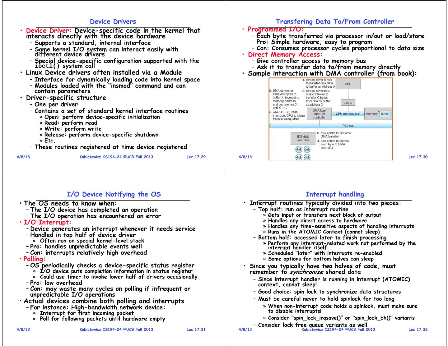
8 . Device Drivers Transfering Data To/From Controller • Device Driver: Device-specific code in the kernel that • Programmed I/O: interacts directly with the device hardware – Each byte transferred via processor in/out or load/store – Supports a standard, internal interface – Pro: Simple hardware, easy to program – Same kernel I/O system can interact easily with – Con: Consumes processor cycles proportional to data size different device drivers • Direct Memory Access: – Special device-specific configuration supported with the – Give controller access to memory bus ioctl() system call – Ask it to transfer data to/from memory directly • Linux Device drivers often installed via a Module • Sample interaction with DMA controller (from book): – Interface for dynamically loading code into kernel space – Modules loaded with the “insmod” command and can contain parameters • Driver-specific structure – One per driver – Contains a set of standard kernel interface routines » Open: perform device-specific initialization » Read: perform read » Write: perform write » Release: perform device-specific shutdown » Etc. – These routines registered at time device registered 4/8/13 Kubiatowicz CS194-24 ©UCB Fall 2013 Lec 17.29 4/8/13 Kubiatowicz CS194-24 ©UCB Fall 2013 Lec 17.30 I/O Device Notifying the OS Interrupt handling • The OS needs to know when: • Interrupt routines typically divided into two pieces: – The I/O device has completed an operation – Top half: run as interrupt routine – The I/O operation has encountered an error » Gets input or transfers next block of output • I/O Interrupt: » Handles any direct access to hardware » Handles any time-sensitive aspects of handling interrupts – Device generates an interrupt whenever it needs service » Runs in the ATOMIC Context (cannot sleep) – Handled in top half of device driver – Bottom half: accessed later to finish processing » Often run on special kernel-level stack » Perform any interrupt-related work not performed by the – Pro: handles unpredictable events well interrupt handler itself – Con: interrupts relatively high overhead » Scheduled “later” with interrupts re-enabled • Polling: » Some options for bottom halves can sleep – OS periodically checks a device-specific status register • Since you typically have two halves of code, must » I/O device puts completion information in status register remember to synchronize shared data » Could use timer to invoke lower half of drivers occasionally – Since interrupt handler is running in interrupt (ATOMIC) – Pro: low overhead context, cannot sleep! – Con: may waste many cycles on polling if infrequent or – Good choice: spin lock to synchronize data structures unpredictable I/O operations • Actual devices combine both polling and interrupts – Must be careful never to hold spinlock for too long – For instance: High-bandwidth network device: » When non-interrupt code holds a spinlock, must make sure » Interrupt for first incoming packet to disable interrupts! » Poll for following packets until hardware empty » Consider “spin_lock_irqsave()” or “spin_lock_bh()” variants – Consider lock free queue variants as well 4/8/13 Kubiatowicz CS194-24 ©UCB Fall 2013 Lec 17.31 4/8/13 Kubiatowicz CS194-24 ©UCB Fall 2013 Lec 17.32
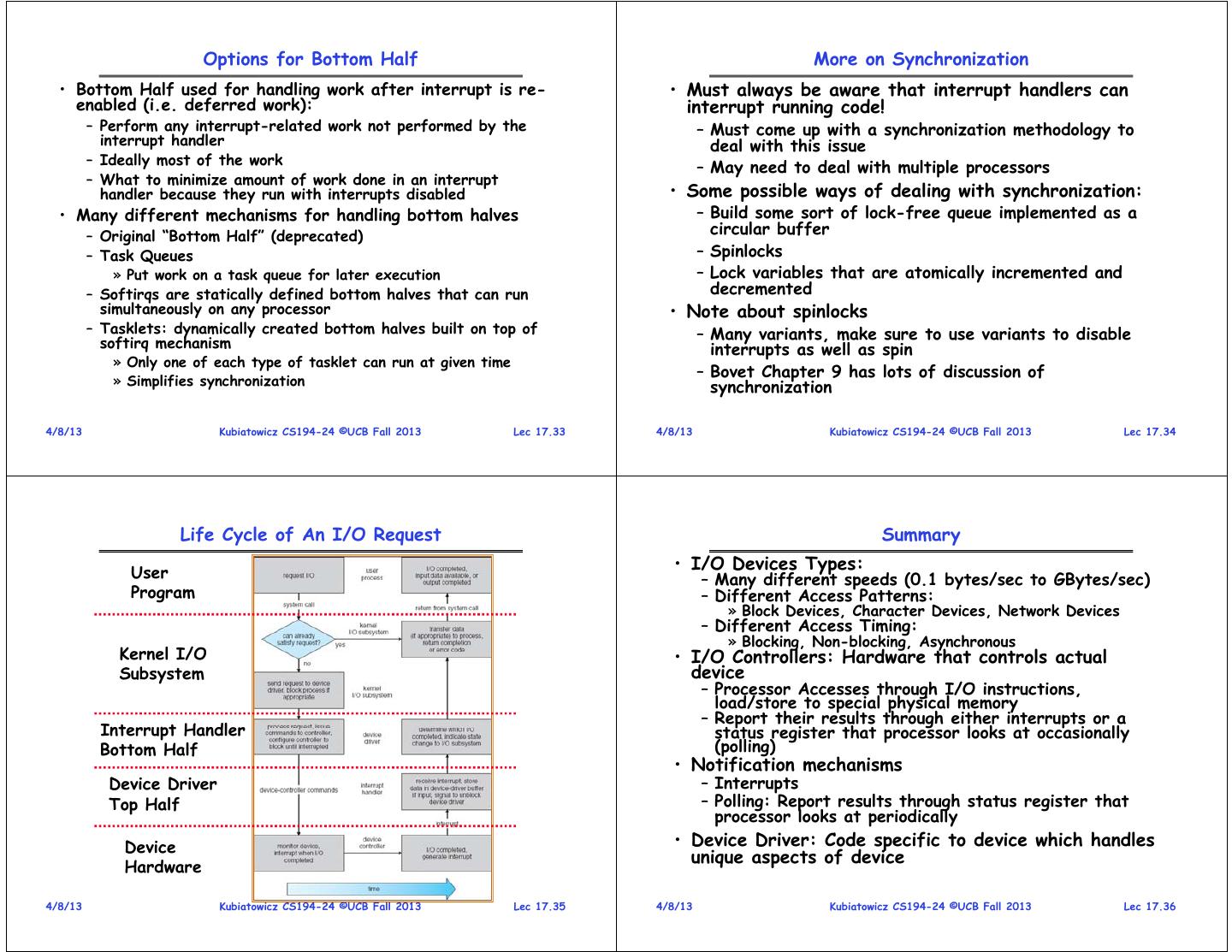
9 . Options for Bottom Half More on Synchronization • Bottom Half used for handling work after interrupt is re- • Must always be aware that interrupt handlers can enabled (i.e. deferred work): interrupt running code! – Perform any interrupt-related work not performed by the – Must come up with a synchronization methodology to interrupt handler deal with this issue – Ideally most of the work – May need to deal with multiple processors – What to minimize amount of work done in an interrupt handler because they run with interrupts disabled • Some possible ways of dealing with synchronization: • Many different mechanisms for handling bottom halves – Build some sort of lock-free queue implemented as a – Original “Bottom Half” (deprecated) circular buffer – Task Queues – Spinlocks » Put work on a task queue for later execution – Lock variables that are atomically incremented and – Softirqs are statically defined bottom halves that can run decremented simultaneously on any processor • Note about spinlocks – Tasklets: dynamically created bottom halves built on top of – Many variants, make sure to use variants to disable softirq mechanism interrupts as well as spin » Only one of each type of tasklet can run at given time – Bovet Chapter 9 has lots of discussion of » Simplifies synchronization synchronization 4/8/13 Kubiatowicz CS194-24 ©UCB Fall 2013 Lec 17.33 4/8/13 Kubiatowicz CS194-24 ©UCB Fall 2013 Lec 17.34 Life Cycle of An I/O Request Summary User • I/O Devices Types: – Many different speeds (0.1 bytes/sec to GBytes/sec) Program – Different Access Patterns: » Block Devices, Character Devices, Network Devices – Different Access Timing: » Blocking, Non-blocking, Asynchronous Kernel I/O • I/O Controllers: Hardware that controls actual Subsystem device – Processor Accesses through I/O instructions, load/store to special physical memory – Report their results through either interrupts or a Interrupt Handler status register that processor looks at occasionally Bottom Half (polling) • Notification mechanisms Device Driver – Interrupts Top Half – Polling: Report results through status register that processor looks at periodically Device • Device Driver: Code specific to device which handles unique aspects of device Hardware 4/8/13 Kubiatowicz CS194-24 ©UCB Fall 2013 Lec 17.35 4/8/13 Kubiatowicz CS194-24 ©UCB Fall 2013 Lec 17.36


