- 快召唤伙伴们来围观吧
- 微博 QQ QQ空间 贴吧
- 文档嵌入链接
- 复制
- 微信扫一扫分享
- 已成功复制到剪贴板
038-Planning and Navigation
展开查看详情
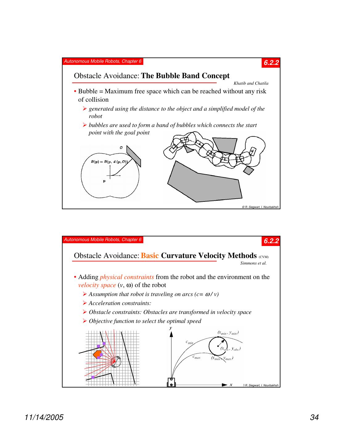
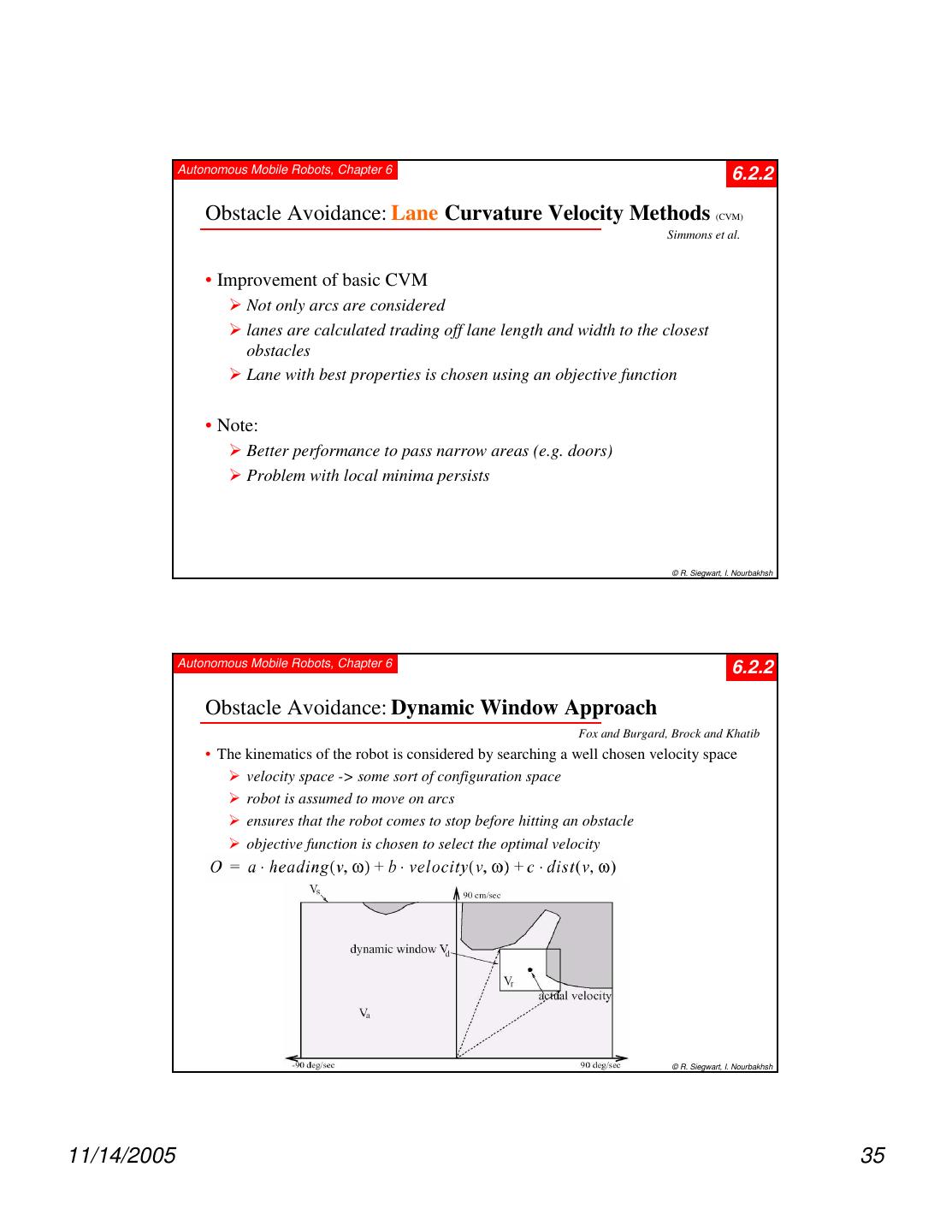
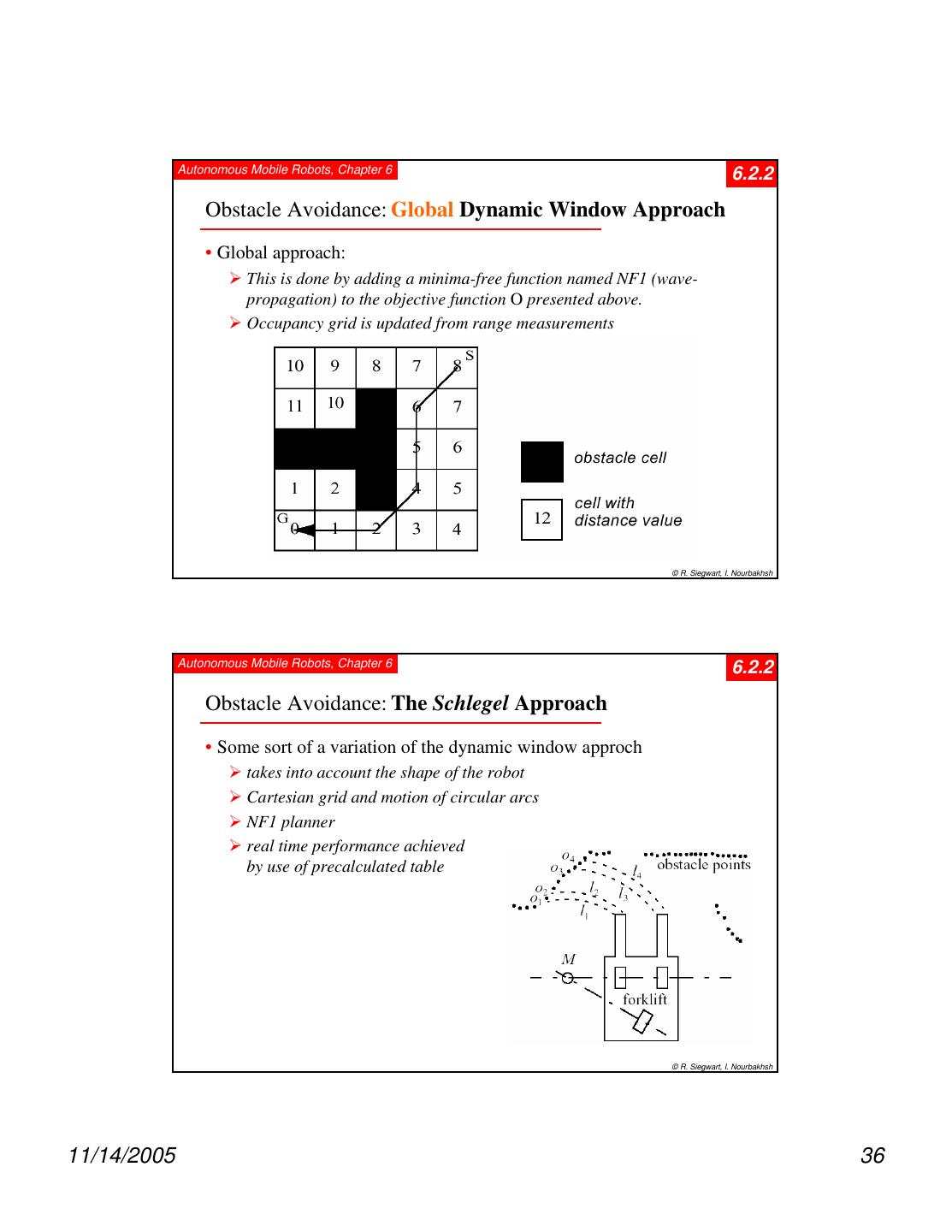
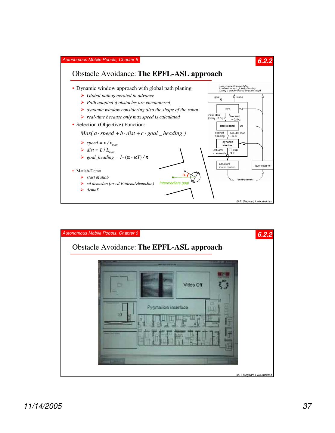
1 . Autonomous Mobile Robots, Chapter 6 6 Planning and Navigation Where am I going? How do I get there? ? Localization "Position" Cognition Global Map Environment Model Path Local Map Perception Real World Motion Control Environment © R. Siegwart, I. Nourbakhsh Autonomous Mobile Robots, Chapter 6 6.2 Competencies for Navigation I • Cognition / Reasoning : is the ability to decide what actions are required to achieve a certain goal in a given situation (belief state). decisions ranging from what path to take to what information on the environment to use. • Today’s industrial robots can operate without any cognition (reasoning) because their environment is static and very structured. • In mobile robotics, cognition and reasoning is primarily of geometric nature, such as picking safe path or determining where to go next. already been largely explored in literature for cases in which complete information about the current situation and the environment exists (e.g. sales man problem). © R. Siegwart, I. Nourbakhsh 11/14/2005 1
2 . Autonomous Mobile Robots, Chapter 6 6.2 Competencies for Navigation II • However, in mobile robotics the knowledge of about the environment and situation is usually only partially known and is uncertain. makes the task much more difficult requires multiple tasks running in parallel, some for planning (global), some to guarantee “survival of the robot”. • Robot control can usually be decomposed in various behaviors or functions e.g. wall following, localization, path generation or obstacle avoidance. • In this chapter we are concerned with path planning and navigation, except the low lever motion control and localization. • We can generally distinguish between (global) path planning and (local) obstacle avoidance. © R. Siegwart, I. Nourbakhsh Autonomous Mobile Robots, Chapter 6 6.2.1 Global Path Planing • Assumption: there exists a good enough map of the environment for navigation. Topological or metric or a mixture between both. • First step: Representation of the environment by a road-map (graph), cells or a potential field. The resulting discrete locations or cells allow then to use standard planning algorithms. • Examples: Visibility Graph Voronoi Diagram Cell Decomposition -> Connectivity Graph Potential Field © R. Siegwart, I. Nourbakhsh 11/14/2005 2
3 . Autonomous Mobile Robots, Chapter 6 6.2.1 Path Planning: Configuration Space • State or configuration q can be described with k values qi • What is the configuration space of a mobile robot? © R. Siegwart, I. Nourbakhsh Autonomous Mobile Robots, Chapter 6 6.2.1 Path Planning Overview 1. Road Map, Graph construction 2. Cell decomposition Identify a set of routes within the free Discriminate between free and space occupied cells • Where to put the nodes? • Where to put the cell boundaries? • Topology-based: • Topology- and metric-based: at distinctive locations where features disappear or get visible • Metric-based: 3. Potential Field where features disappear or get visible Imposing a mathematical function over the space © R. Siegwart, I. Nourbakhsh 11/14/2005 3
4 . Autonomous Mobile Robots, Chapter 6 6.2.1 Road-Map Path Planning: Visibility Graph • Shortest path length • Grow obstacles to avoid collisions © R. Siegwart, I. Nourbakhsh Autonomous Mobile Robots, Chapter 6 From Workspace to Configuration Space • In order to model robots as points, the standard practice is to “grow” the obstacles by convolving them with the robot’s dimensions O1 O1 O2 O2 r (xr, yr) Workspace (W) Configuration Space (C) © JR Spletzer 11/14/2005 4
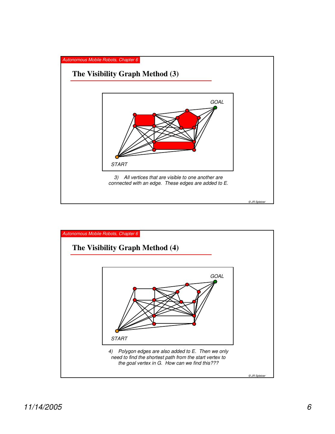
5 . Autonomous Mobile Robots, Chapter 6 The Visibility Graph Method (1) GOAL START 1) Model obstacles as polygons © JR Spletzer Autonomous Mobile Robots, Chapter 6 The Visibility Graph Method (2) GOAL START 2) Construct a graph G(V,E). All polygon vertices are added to V, as are the start and goal positions. © JR Spletzer 11/14/2005 5
6 . Autonomous Mobile Robots, Chapter 6 The Visibility Graph Method (3) GOAL START 3) All vertices that are visible to one another are connected with an edge. These edges are added to E. © JR Spletzer Autonomous Mobile Robots, Chapter 6 The Visibility Graph Method (4) GOAL START 4) Polygon edges are also added to E. Then we only need to find the shortest path from the start vertex to the goal vertex in G. How can we find this??? © JR Spletzer 11/14/2005 6
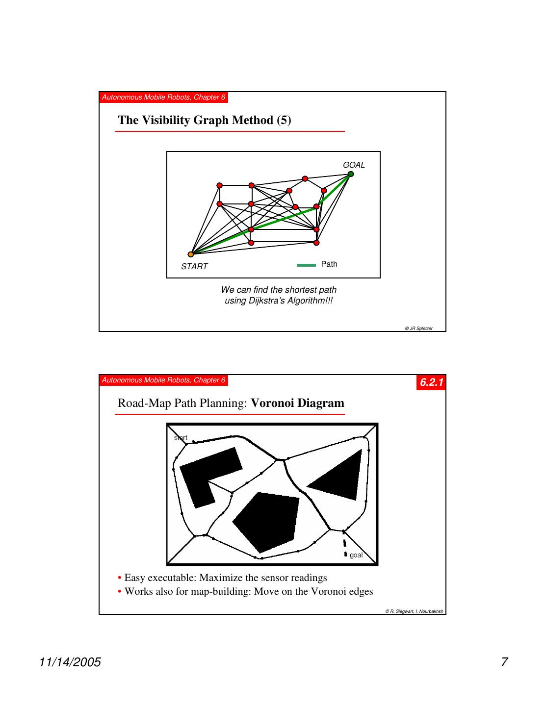
7 . Autonomous Mobile Robots, Chapter 6 The Visibility Graph Method (5) GOAL START Path We can find the shortest path using Dijkstra’s Algorithm!!! © JR Spletzer Autonomous Mobile Robots, Chapter 6 6.2.1 Road-Map Path Planning: Voronoi Diagram • Easy executable: Maximize the sensor readings • Works also for map-building: Move on the Voronoi edges © R. Siegwart, I. Nourbakhsh 11/14/2005 7
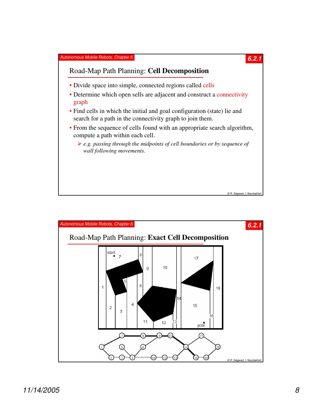
8 . Autonomous Mobile Robots, Chapter 6 6.2.1 Road-Map Path Planning: Cell Decomposition • Divide space into simple, connected regions called cells • Determine which open sells are adjacent and construct a connectivity graph • Find cells in which the initial and goal configuration (state) lie and search for a path in the connectivity graph to join them. • From the sequence of cells found with an appropriate search algorithm, compute a path within each cell. e.g. passing through the midpoints of cell boundaries or by sequence of wall following movements. © R. Siegwart, I. Nourbakhsh Autonomous Mobile Robots, Chapter 6 6.2.1 Road-Map Path Planning: Exact Cell Decomposition © R. Siegwart, I. Nourbakhsh 11/14/2005 8
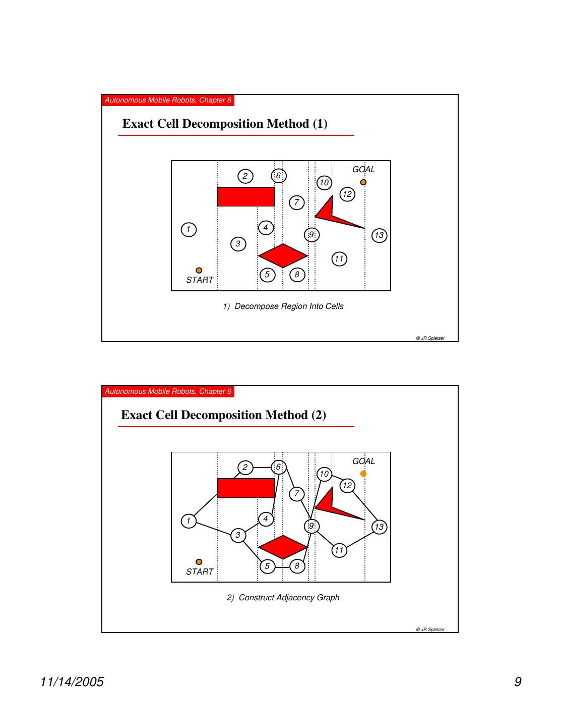
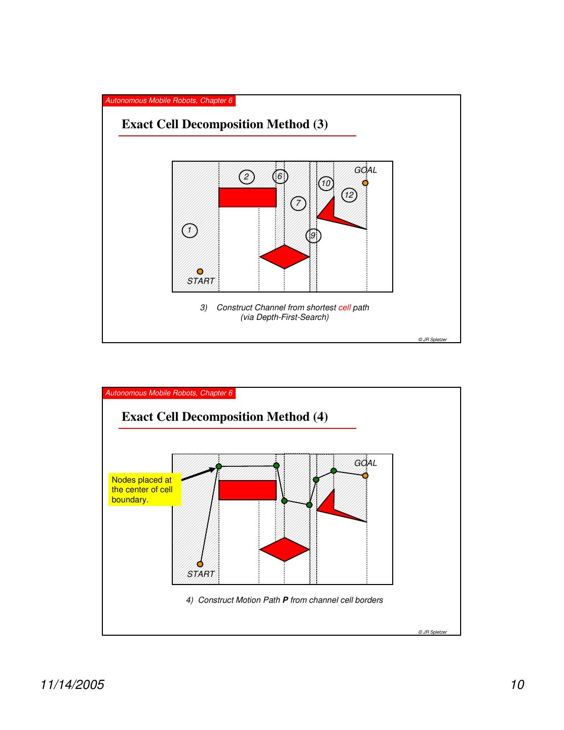
9 . Autonomous Mobile Robots, Chapter 6 Exact Cell Decomposition Method (1) GOAL 2 6 10 12 7 1 4 9 13 3 11 5 8 START 1) Decompose Region Into Cells © JR Spletzer Autonomous Mobile Robots, Chapter 6 Exact Cell Decomposition Method (2) GOAL 2 6 10 12 7 1 4 9 13 3 11 5 8 START 2) Construct Adjacency Graph © JR Spletzer 11/14/2005 9
10 . Autonomous Mobile Robots, Chapter 6 Exact Cell Decomposition Method (3) GOAL 2 6 10 12 7 1 9 START 3) Construct Channel from shortest cell path (via Depth-First-Search) © JR Spletzer Autonomous Mobile Robots, Chapter 6 Exact Cell Decomposition Method (4) GOAL Nodes placed at the center of cell boundary. START 4) Construct Motion Path P from channel cell borders © JR Spletzer 11/14/2005 10
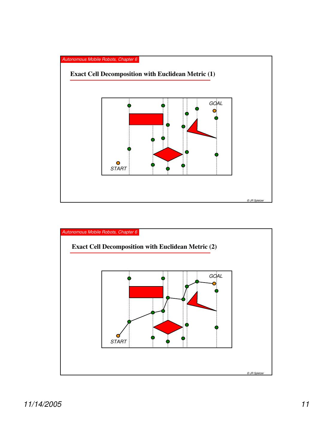
11 . Autonomous Mobile Robots, Chapter 6 Exact Cell Decomposition with Euclidean Metric (1) GOAL START © JR Spletzer Autonomous Mobile Robots, Chapter 6 Exact Cell Decomposition with Euclidean Metric (2) GOAL START © JR Spletzer 11/14/2005 11
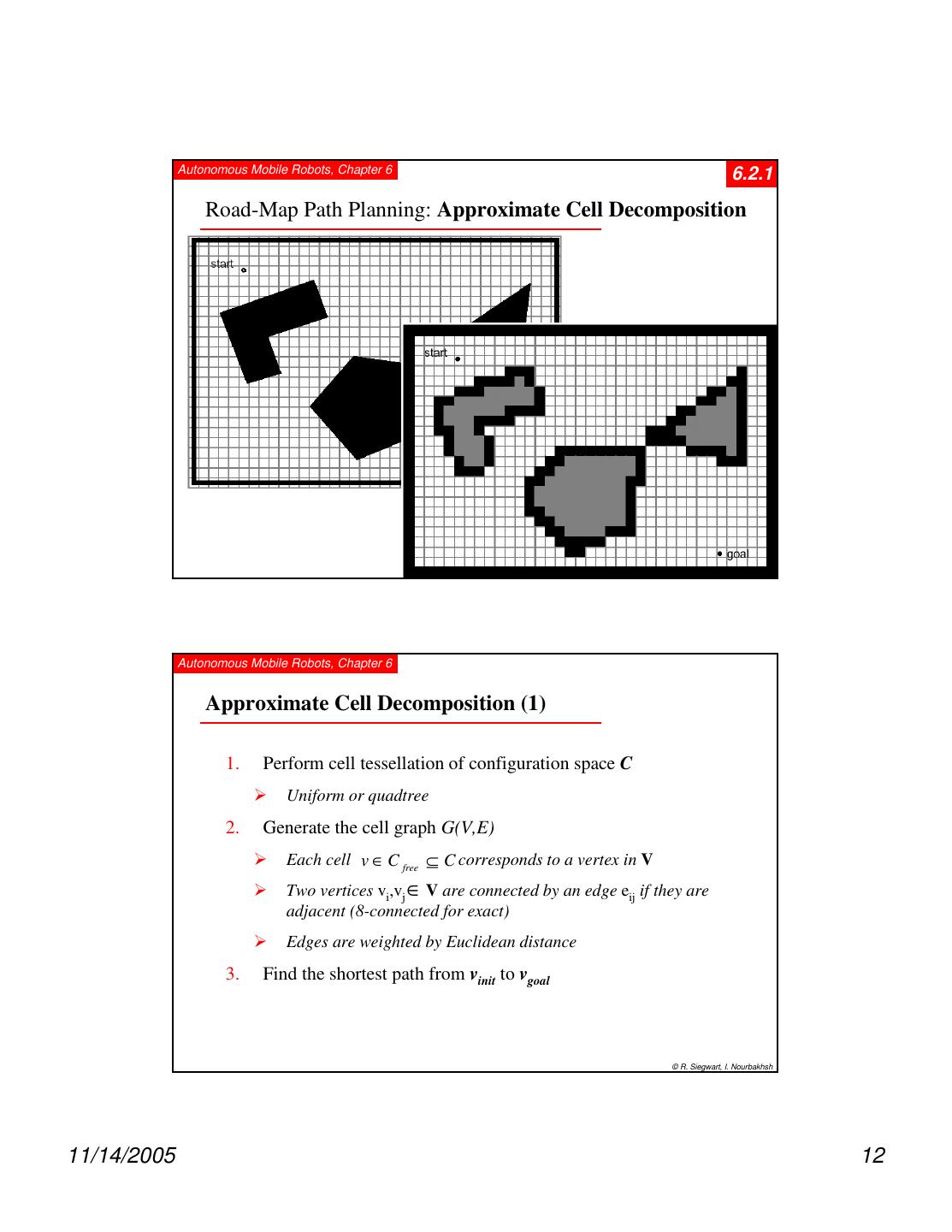
12 . Autonomous Mobile Robots, Chapter 6 6.2.1 Road-Map Path Planning: Approximate Cell Decomposition © R. Siegwart, I. Nourbakhsh Autonomous Mobile Robots, Chapter 6 Approximate Cell Decomposition (1) 1. Perform cell tessellation of configuration space C Uniform or quadtree 2. Generate the cell graph G(V,E) Each cell v ∈ C free ⊆ C corresponds to a vertex in V Two vertices vi,vj ∈ V are connected by an edge eij if they are adjacent (8-connected for exact) Edges are weighted by Euclidean distance 3. Find the shortest path from vinit to vgoal © R. Siegwart, I. Nourbakhsh 11/14/2005 12
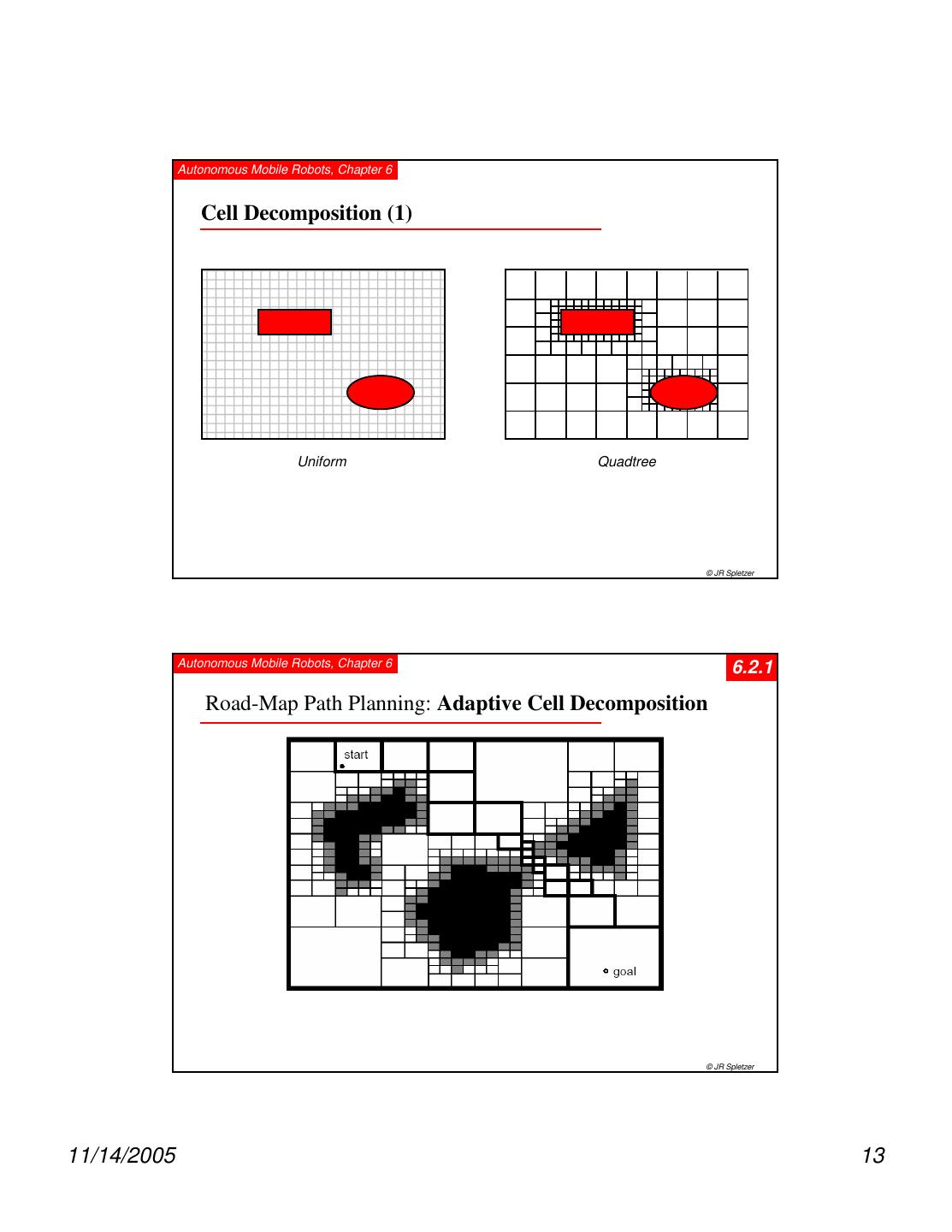
13 . Autonomous Mobile Robots, Chapter 6 Cell Decomposition (1) Uniform Quadtree © JR Spletzer Autonomous Mobile Robots, Chapter 6 6.2.1 Road-Map Path Planning: Adaptive Cell Decomposition © JR Spletzer 11/14/2005 13
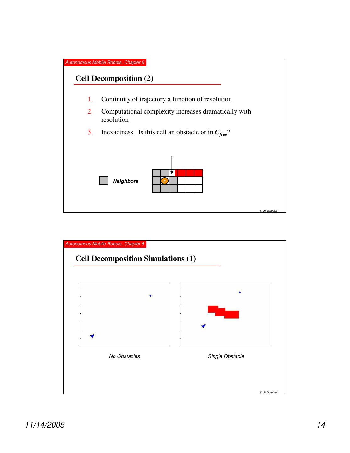
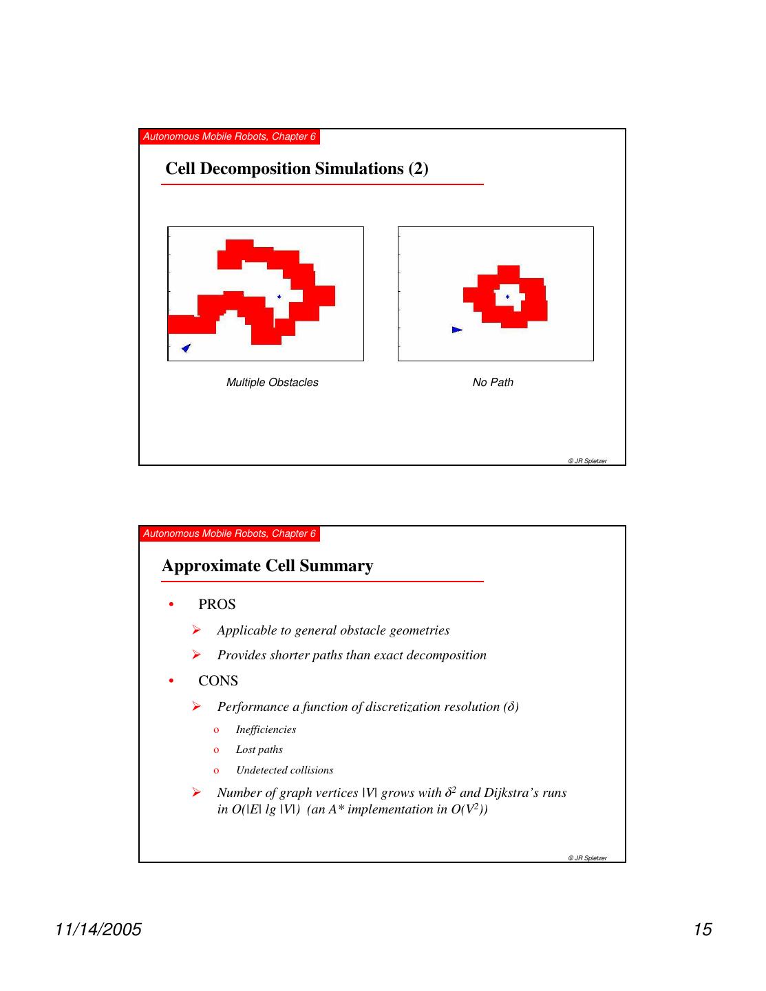
14 . Autonomous Mobile Robots, Chapter 6 Cell Decomposition (2) 1. Continuity of trajectory a function of resolution 2. Computational complexity increases dramatically with resolution 3. Inexactness. Is this cell an obstacle or in Cfree? Neighbors r © JR Spletzer Autonomous Mobile Robots, Chapter 6 Cell Decomposition Simulations (1) No Obstacles Single Obstacle © JR Spletzer 11/14/2005 14
15 . Autonomous Mobile Robots, Chapter 6 Cell Decomposition Simulations (2) Multiple Obstacles No Path © JR Spletzer Autonomous Mobile Robots, Chapter 6 Approximate Cell Summary • PROS Applicable to general obstacle geometries Provides shorter paths than exact decomposition • CONS δ Performance a function of discretization resolution ( ) o Inefficiencies o Lost paths o Undetected collisions Number of graph vertices |V| grows with 2 and Dijkstra’s runs δ in O(|E| lg |V|) (an A* implementation in O(V2)) © JR Spletzer 11/14/2005 15
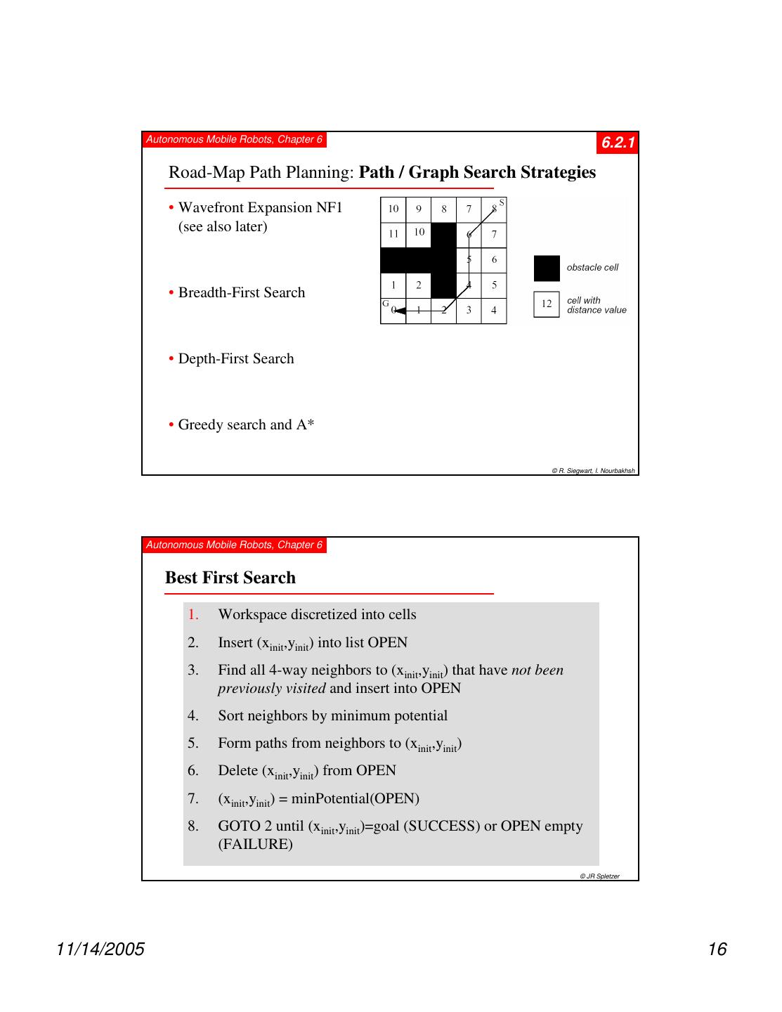
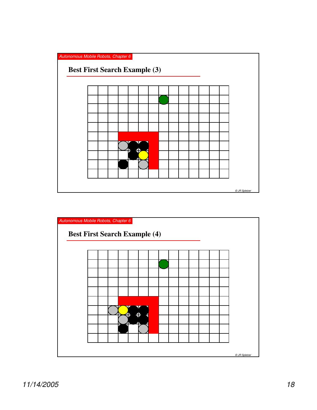
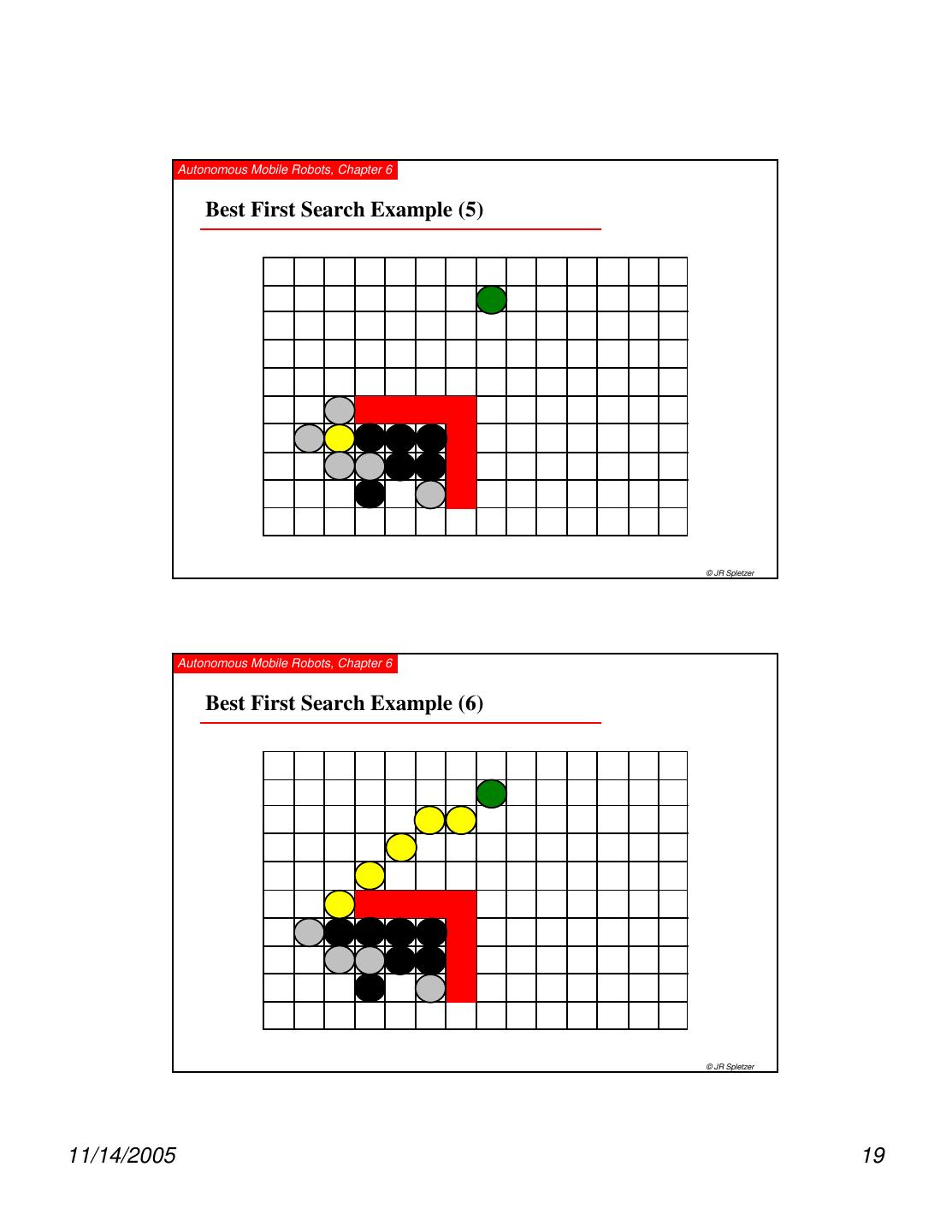
16 . Autonomous Mobile Robots, Chapter 6 6.2.1 Road-Map Path Planning: Path / Graph Search Strategies • Wavefront Expansion NF1 (see also later) • Breadth-First Search • Depth-First Search • Greedy search and A* © R. Siegwart, I. Nourbakhsh Autonomous Mobile Robots, Chapter 6 Best First Search 1. Workspace discretized into cells 2. Insert (xinit,yinit) into list OPEN 3. Find all 4-way neighbors to (xinit,yinit) that have not been previously visited and insert into OPEN 4. Sort neighbors by minimum potential 5. Form paths from neighbors to (xinit,yinit) 6. Delete (xinit,yinit) from OPEN 7. (xinit,yinit) = minPotential(OPEN) 8. GOTO 2 until (xinit,yinit)=goal (SUCCESS) or OPEN empty (FAILURE) © JR Spletzer 11/14/2005 16
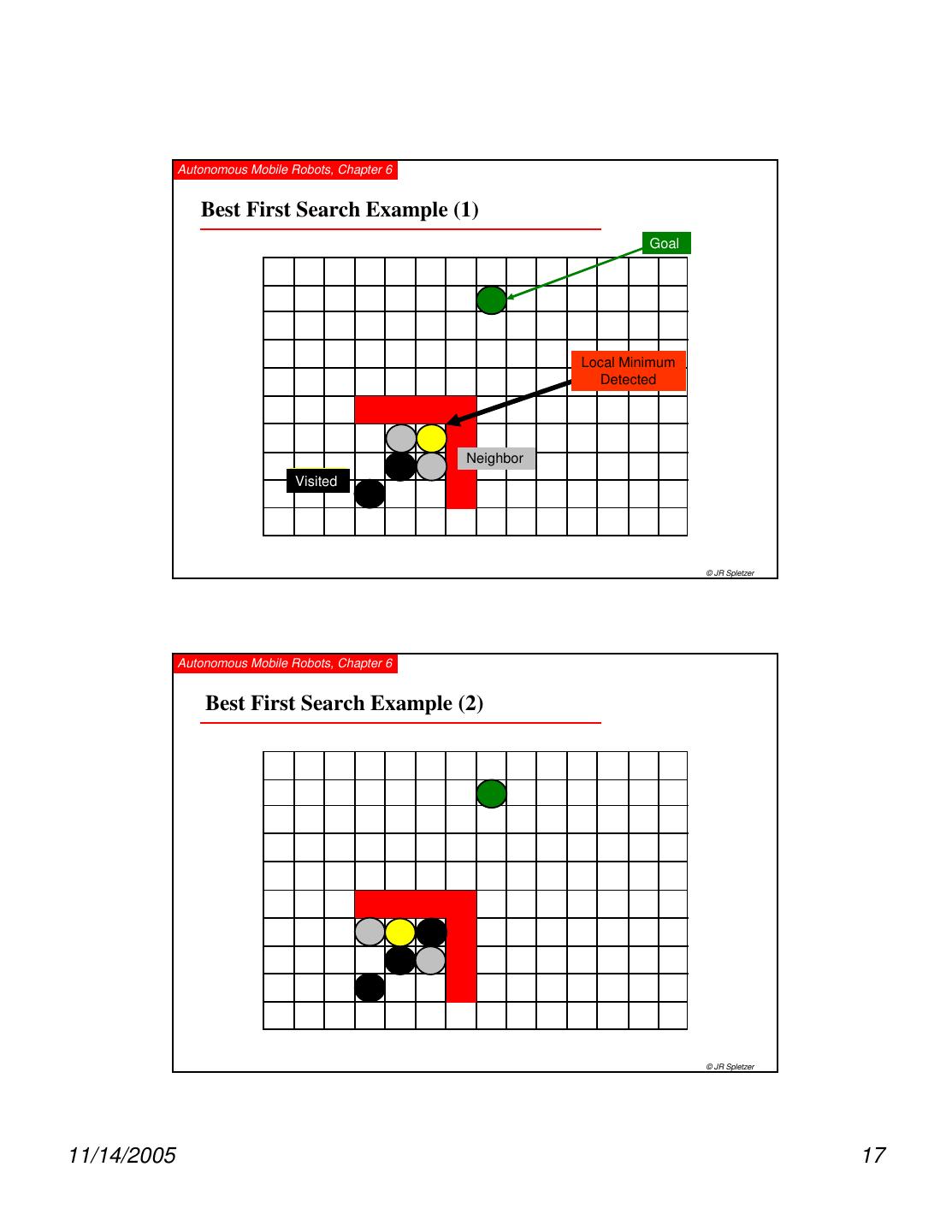
17 . Autonomous Mobile Robots, Chapter 6 Best First Search Example (1) Goal Local Minimum Detected Neighbor Robot Visited © JR Spletzer Autonomous Mobile Robots, Chapter 6 Best First Search Example (2) © JR Spletzer 11/14/2005 17
18 . Autonomous Mobile Robots, Chapter 6 Best First Search Example (3) © JR Spletzer Autonomous Mobile Robots, Chapter 6 Best First Search Example (4) © JR Spletzer 11/14/2005 18
19 . Autonomous Mobile Robots, Chapter 6 Best First Search Example (5) © JR Spletzer Autonomous Mobile Robots, Chapter 6 Best First Search Example (6) © JR Spletzer 11/14/2005 19
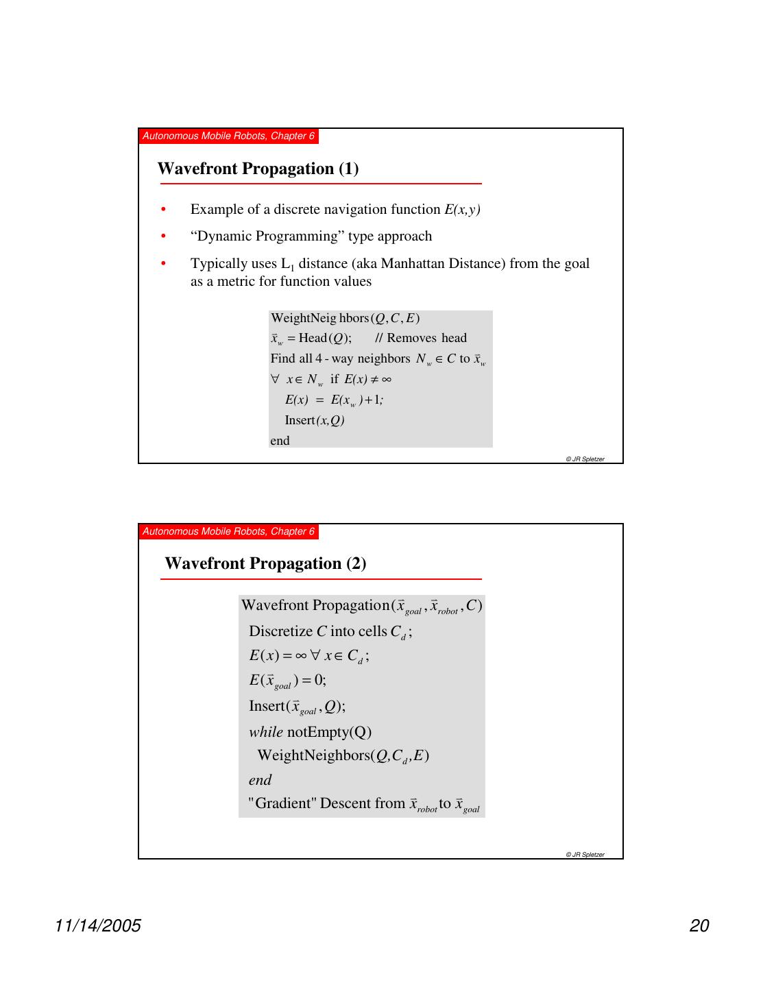
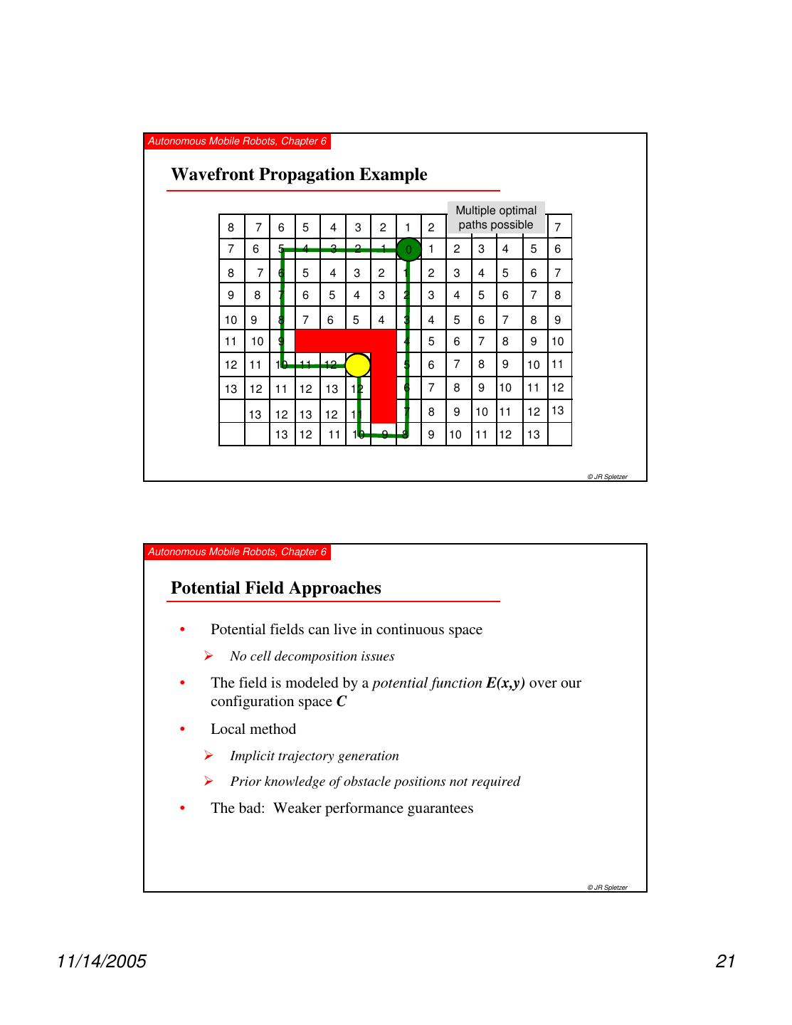
20 . Autonomous Mobile Robots, Chapter 6 Wavefront Propagation (1) • Example of a discrete navigation function E(x,y) • “Dynamic Programming” type approach • Typically uses L1 distance (aka Manhattan Distance) from the goal as a metric for function values WeightNeig hbors (Q , C , E ) v x w = Head (Q ); // Removes head v Find all 4 - way neighbors N w ∈ C to x w ∀ x ∈ N w if E(x) ≠ ∞ E(x) = E(x w ) + 1; Insert (x,Q) end © JR Spletzer Autonomous Mobile Robots, Chapter 6 Wavefront Propagation (2) v v Wavefront Propagatio n ( x goal , xrobot , C ) Discretize C into cells C d ; E ( x) = ∞ ∀ x ∈ Cd ; v E ( x goal ) = 0; v Insert ( x goal , Q ); while notEmpty(Q ) WeightNeighbors( Q,Cd ,E ) end v v " Gradient" Descent from xrobot to x goal © JR Spletzer 11/14/2005 20
21 . Autonomous Mobile Robots, Chapter 6 Wavefront Propagation Example Multiple optimal 8 7 6 5 4 3 2 1 2 3paths 4 possible 5 6 7 7 6 5 4 3 2 1 0 1 2 3 4 5 6 8 7 6 5 4 3 2 1 2 3 4 5 6 7 9 8 7 6 5 4 3 2 3 4 5 6 7 8 10 9 8 7 6 5 4 3 4 5 6 7 8 9 11 10 9 4 5 6 7 8 9 10 12 11 10 11 12 13 5 6 7 8 9 10 11 13 12 11 12 13 12 6 7 8 9 10 11 12 13 12 13 12 11 7 8 9 10 11 12 13 13 12 11 10 9 8 9 10 11 12 13 © JR Spletzer Autonomous Mobile Robots, Chapter 6 Potential Field Approaches • Potential fields can live in continuous space No cell decomposition issues • The field is modeled by a potential function E(x,y) over our configuration space C • Local method Implicit trajectory generation Prior knowledge of obstacle positions not required • The bad: Weaker performance guarantees © JR Spletzer 11/14/2005 21
22 . Autonomous Mobile Robots, Chapter 6 6.2.1 Potential Field Path Planning • Robot is treated as a point under the influence of an artificial potential field. Generated robot movement is similar to a ball rolling down the hill Goal generates attractive force Obstacle are repulsive forces © R. Siegwart, I. Nourbakhsh Autonomous Mobile Robots, Chapter 6 Flashback: What is the Gradient? • In 2D, the gradient of a function f is defined as ∂f ∂f ∇f = xˆ + yˆ ∂x ∂y • The gradient points in the direction where the derivative has the largest value (the greatest rate of increase in the value of f) • The gradient descent optimization algorithm searches in the opposite direction of the gradient to find the minimum of a function • Potential field methods employ a similar approach © JR Spletzer 11/14/2005 22
23 . Autonomous Mobile Robots, Chapter 6 Potential Fields for Motion Planning Using Gradient Descent GradientDescent( xinit , x final ,−∇E ) while xinit ≠ x final ∇E xinit = xinit − δ ; // Move δ in direction − ∇E ∇E end Note that in practice, we will stop within some tolerance (like ) of the final position δ to account for positional uncertainties, etc. Also note that the step size must be small δ enough to ensure that we do not collide with an obstacle or overshoot our goal position. © JR Spletzer Autonomous Mobile Robots, Chapter 6 Generating the Potential Field A Parabolic Well for Attracting to Goal 1 x E( x) = ( x − xgoal )T ( x − xgoal ) x = w 2 yw ∇E( x) = x − xgoal NOTE: x is a vector corresponding to a position in the workspace © JR Spletzer 11/14/2005 23
24 . Autonomous Mobile Robots, Chapter 6 Gaussian Obstacle Potential Function ( x− µ )2 ( y − µ y )2 − x + Gaussian centered 1 2σ 2 2σ y2 f ( x) = x at the obstacle e coordinates 2π σ x2σ y2 For a symmetric 2D Gaussians 1 v 2 − x γ v 2 1 2σ 2 − x f ( x) = e = βe 2 2πσ 2 © JR Spletzer Autonomous Mobile Robots, Chapter 6 Parabolic Well for Goal Exponential Source for Obstacle −γ v v 2 r 1 v v T v v x − xobs E( x ) = ( x − xgoal ) ( x − xgoal ) + βe 2 2 −γ v v 2 v v v v v x − xobs ∇E( x) = x − xgoal − γ ( x − xobs )βe 2 © JR Spletzer 11/14/2005 24
25 . Autonomous Mobile Robots, Chapter 6 Parabolic Well /Exponential Source Unstable Equilibrium Example −γ v v 2 r 1 v v v v x − xobs E( x ) = ( x − xgoal )T ( x − xgoal ) + βe 2 2 −γ v v 2 v v v v v x − xobs ∇E( x) = x − xgoal − γ ( x − xobs )βe 2 © JR Spletzer Autonomous Mobile Robots, Chapter 6 Parabolic Well Goal & Two Exponential Source Obstacles (1) n −γ i v v 2 r 1 v v v v x − xobs ( i ) E( x) = ( x − xgoal )T ( x − xgoal ) + ∑ βi e 2 2 i =1 n −γ i v v 2 v v v v v x − xobs ( i ) ∇E( x) = x − xgoal − ∑γ i ( x − xobs(i ) )βi e 2 i =1 © JR Spletzer 11/14/2005 25
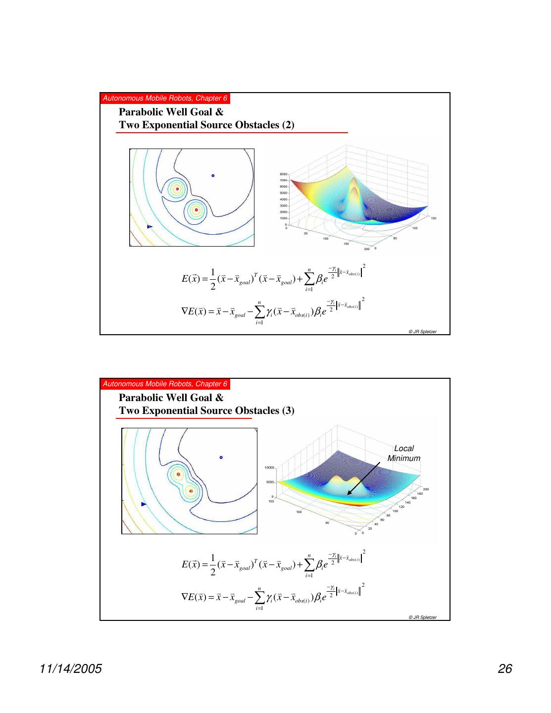
26 . Autonomous Mobile Robots, Chapter 6 Parabolic Well Goal & Two Exponential Source Obstacles (2) n −γ i v v 2 r 1 v v v v x − xobs ( i ) E( x) = ( x − xgoal )T ( x − xgoal ) + ∑ βi e 2 2 i =1 n −γ i v v 2 v v v v v x − xobs ( i ) ∇E( x) = x − xgoal − ∑γ i ( x − xobs(i ) )βi e 2 i =1 © JR Spletzer Autonomous Mobile Robots, Chapter 6 Parabolic Well Goal & Two Exponential Source Obstacles (3) Local Minimum n −γ i v v 2 r 1 v v v v x − xobs ( i ) E( x) = ( x − xgoal )T ( x − xgoal ) + ∑ βi e 2 2 i =1 n −γ i v v 2 v v v v v x − xobs ( i ) ∇E( x) = x − xgoal − ∑γ i ( x − xobs(i ) )βi e 2 i =1 © JR Spletzer 11/14/2005 26
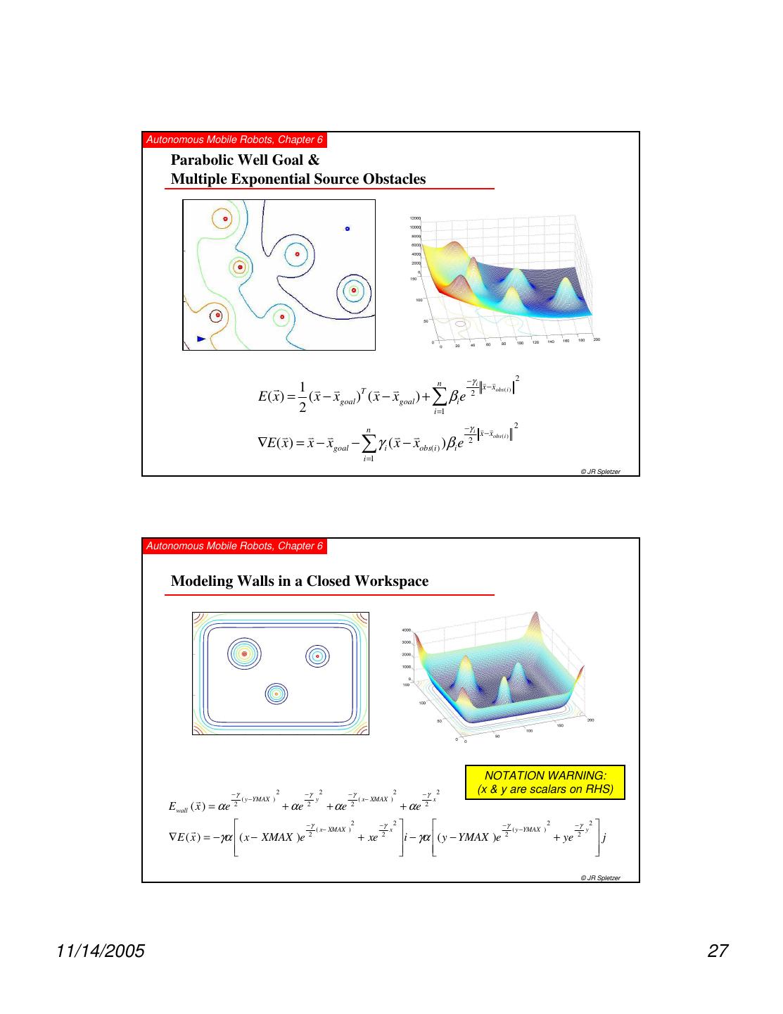
27 . Autonomous Mobile Robots, Chapter 6 Parabolic Well Goal & Multiple Exponential Source Obstacles n −γ i v v 2 r 1 v v v v x − xobs ( i ) E( x) = ( x − xgoal )T ( x − xgoal ) + ∑ βi e 2 2 i =1 n −γ i v v 2 v v v v v x − xobs ( i ) ∇E( x) = x − xgoal − ∑γ i ( x − xobs(i ) )βi e 2 i =1 © JR Spletzer Autonomous Mobile Robots, Chapter 6 Modeling Walls in a Closed Workspace NOTATION WARNING: −γ 2 −γ 2 −γ 2 −γ 2 (x & y are scalars on RHS) r ( y − YMAX ) y ( x− XMAX ) x E wall ( x ) = α e 2 + αe 2 + αe 2 + αe 2 r −γ ( x− XMAX ) 2 −γ 2 x −γ ( y −YMAX ) 2 −γ y 2 ∇ E ( x ) = −γα ( x − XMAX )e 2 + xe 2 i − γα ( y − YMAX )e 2 + ye 2 j © JR Spletzer 11/14/2005 27
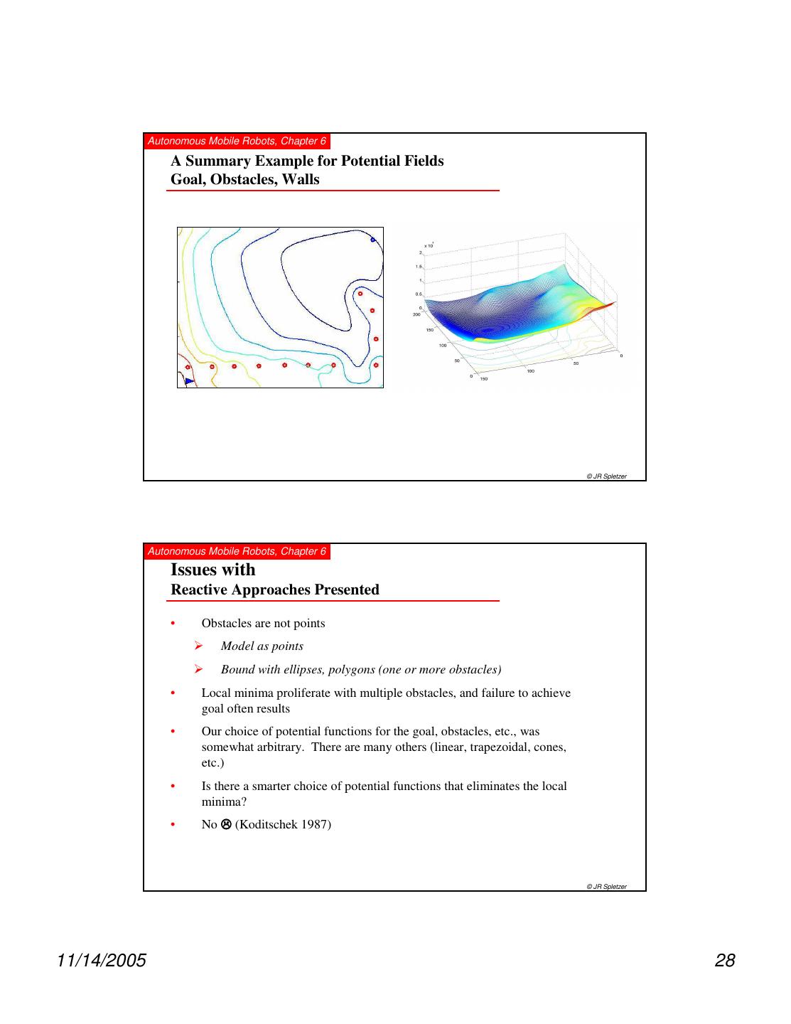
28 . Autonomous Mobile Robots, Chapter 6 A Summary Example for Potential Fields Goal, Obstacles, Walls © JR Spletzer Autonomous Mobile Robots, Chapter 6 Issues with Reactive Approaches Presented • Obstacles are not points Model as points Bound with ellipses, polygons (one or more obstacles) • Local minima proliferate with multiple obstacles, and failure to achieve goal often results • Our choice of potential functions for the goal, obstacles, etc., was somewhat arbitrary. There are many others (linear, trapezoidal, cones, etc.) • Is there a smarter choice of potential functions that eliminates the local minima? • No (Koditschek 1987) © JR Spletzer 11/14/2005 28
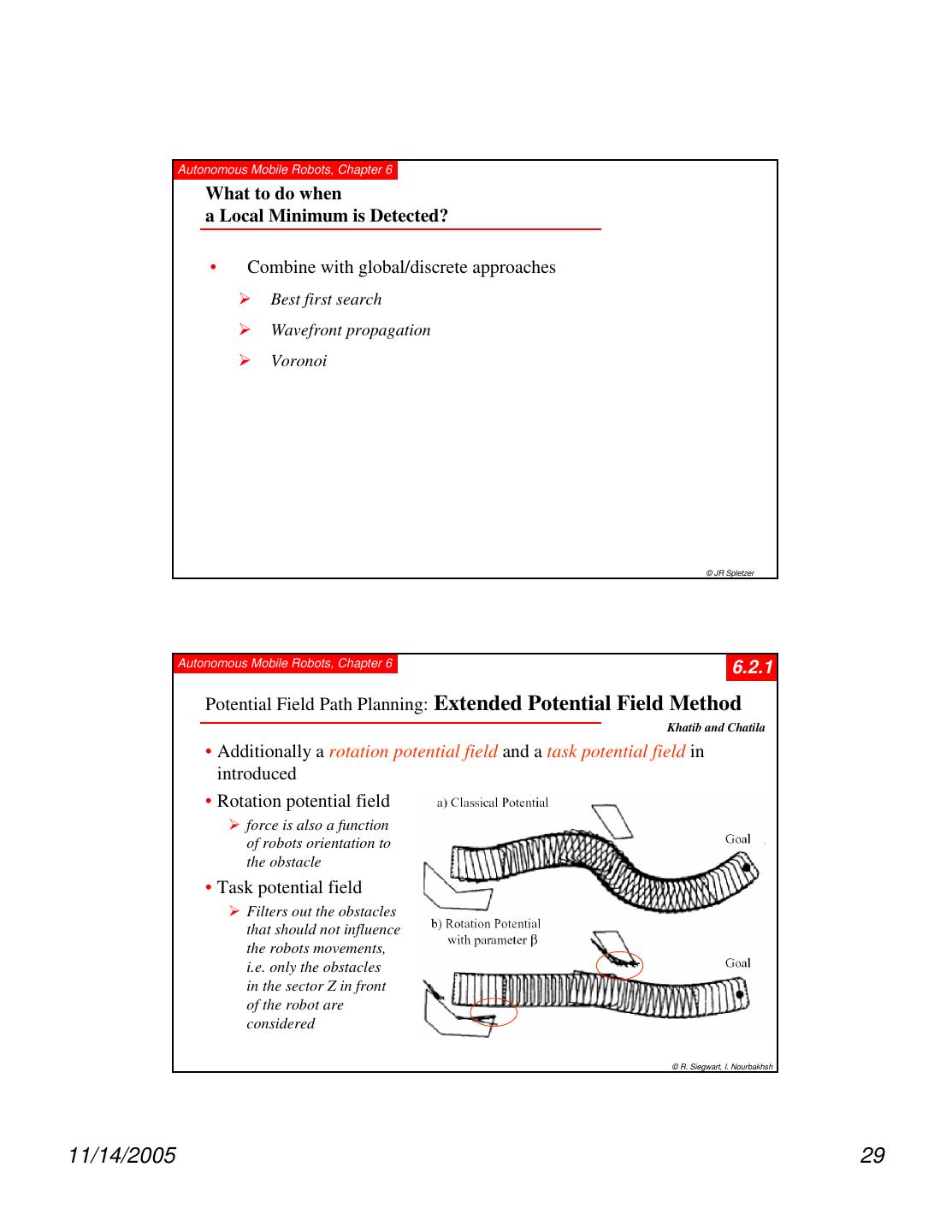
29 . Autonomous Mobile Robots, Chapter 6 What to do when a Local Minimum is Detected? • Combine with global/discrete approaches Best first search Wavefront propagation Voronoi © JR Spletzer Autonomous Mobile Robots, Chapter 6 6.2.1 Potential Field Path Planning: Extended Potential Field Method Khatib and Chatila • Additionally a rotation potential field and a task potential field in introduced • Rotation potential field force is also a function of robots orientation to the obstacle • Task potential field Filters out the obstacles that should not influence the robots movements, i.e. only the obstacles in the sector Z in front of the robot are considered © R. Siegwart, I. Nourbakhsh 11/14/2005 29


