- 快召唤伙伴们来围观吧
- 微博 QQ QQ空间 贴吧
- 文档嵌入链接
- 复制
- 微信扫一扫分享
- 已成功复制到剪贴板
INDUSTRIAL ARMS_Cartesian Coordinate System
展开查看详情
1 .MECHANICAL ROBOT DESIGN
2 .INDUSTRIAL ROBOT ARMS
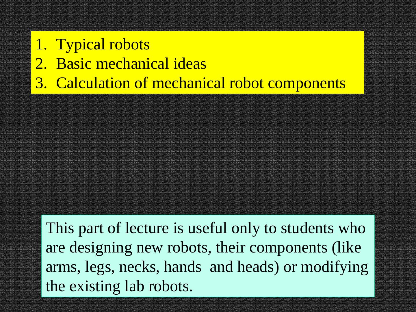
3 .1. Typical robots 2. Basic mechanical ideas 3. Calculation of mechanical robot components This part of lecture is useful only to students who are designing new robots, their components (like arms, legs, necks, hands and heads) or modifying the existing lab robots.
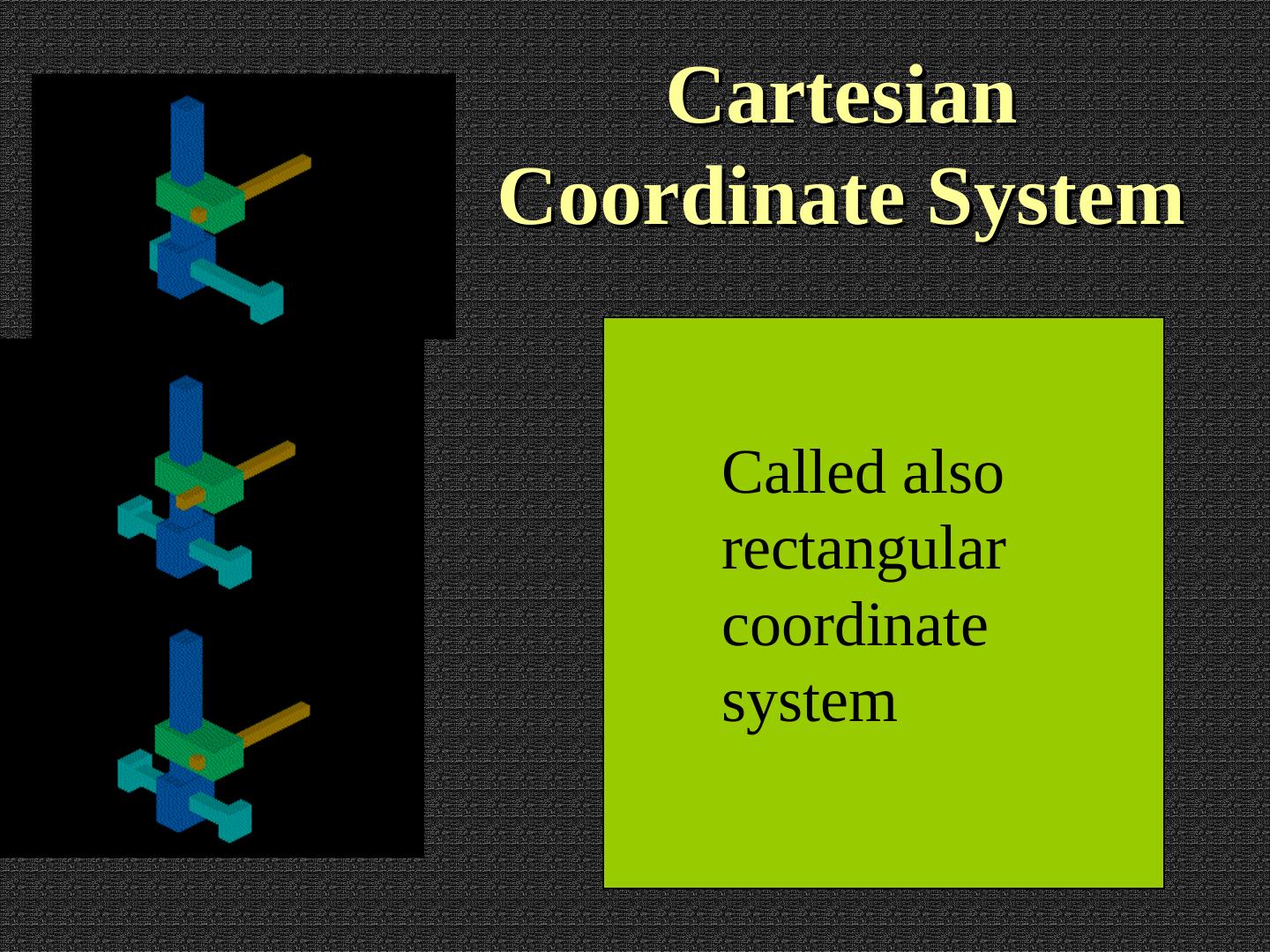
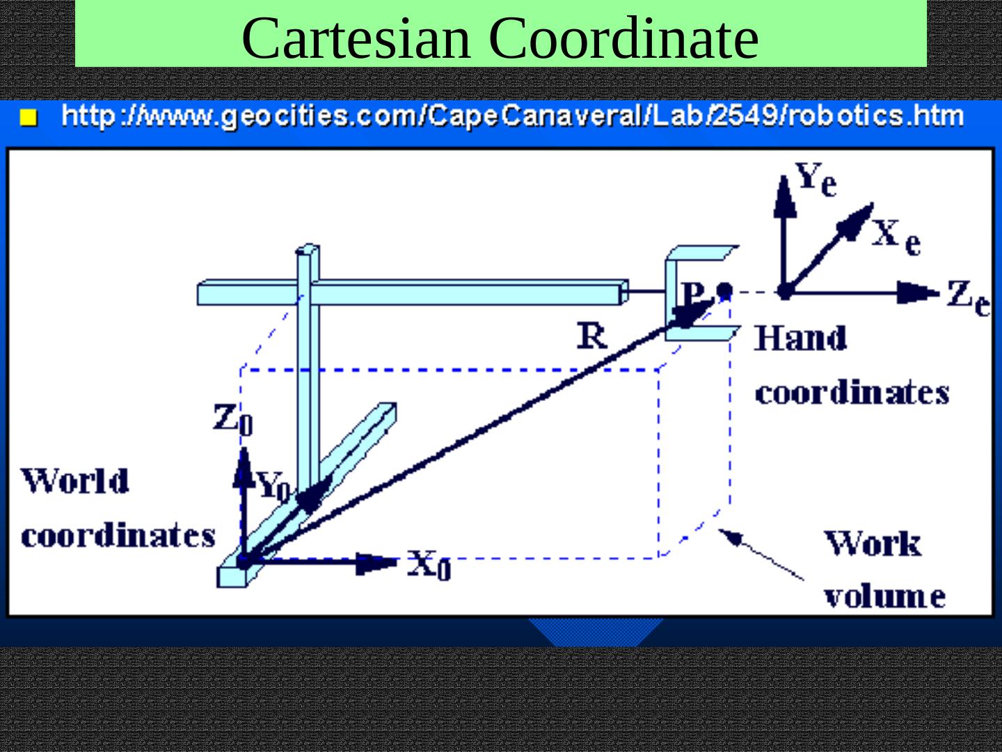
4 . Cartesian Coordinate System Called also rectangular coordinate system
5 . Cartesian Coordinate System X- Axis
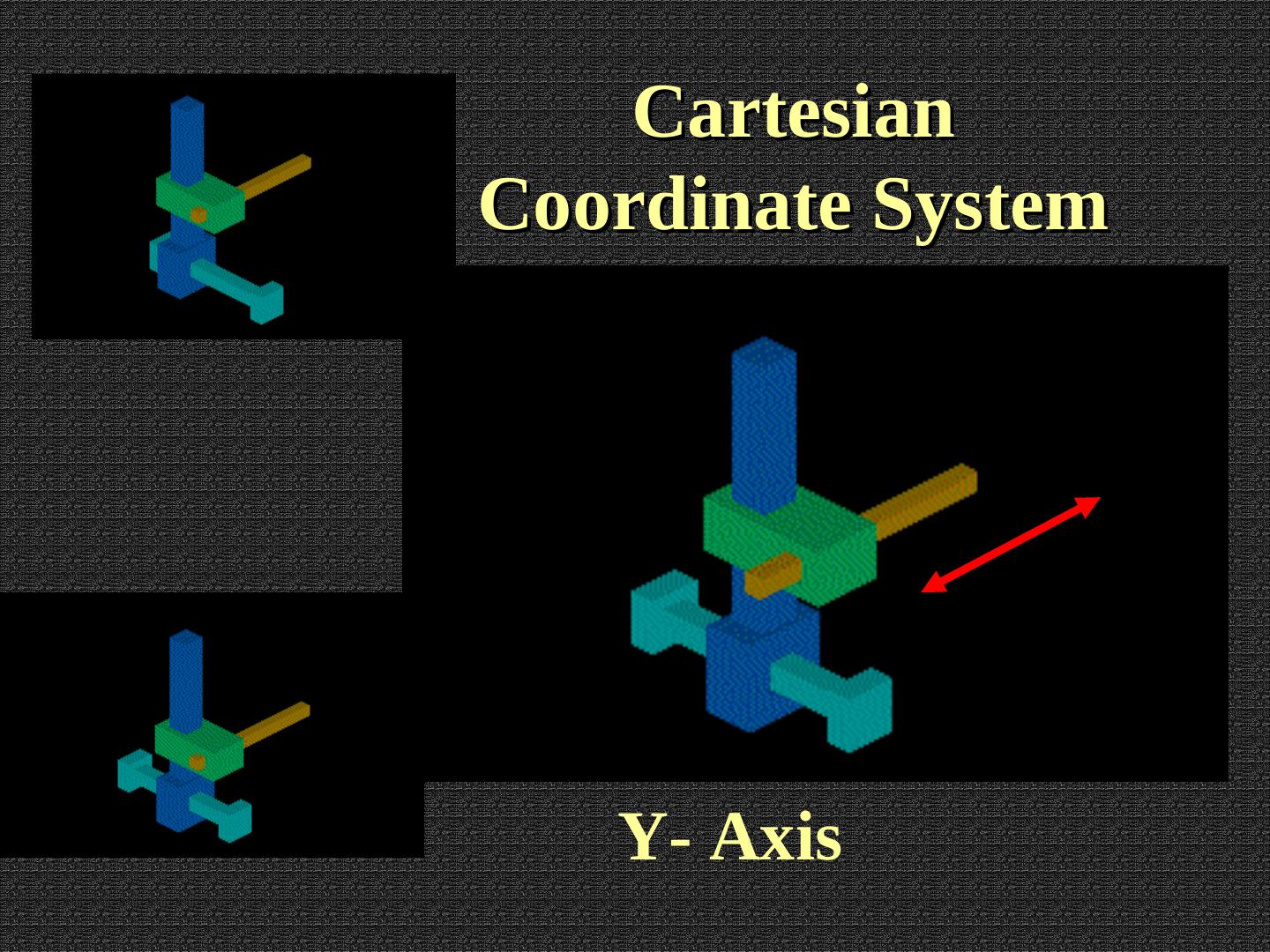
6 . Cartesian Coordinate System Y- Axis
7 . Cartesian Coordinate System Z- Axis
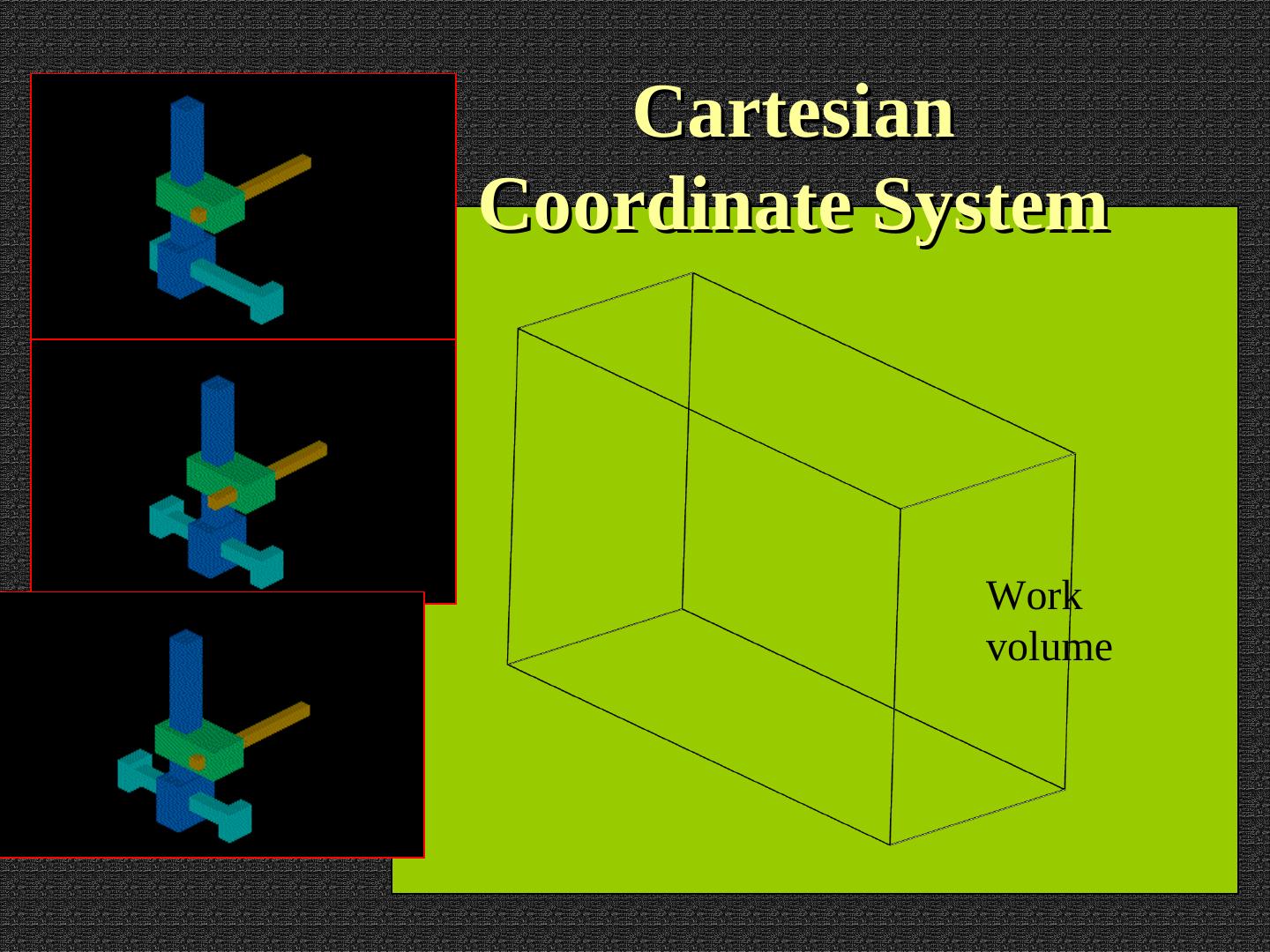
8 . Cartesian Coordinate System Work volume
9 . Cartesian Coordinate Let us distinguish between the world coordinates and the hand coordinates
10 .Cartesian Coordinate
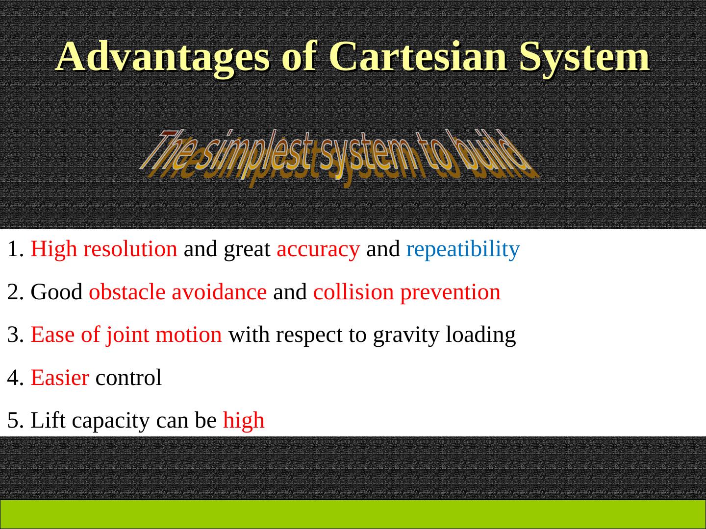
11 . Advantages of Cartesian System 1. High resolution and great accuracy and repeatibility 2. Good obstacle avoidance and collision prevention 3. Ease of joint motion with respect to gravity loading 4. Easier control 5. Lift capacity can be high
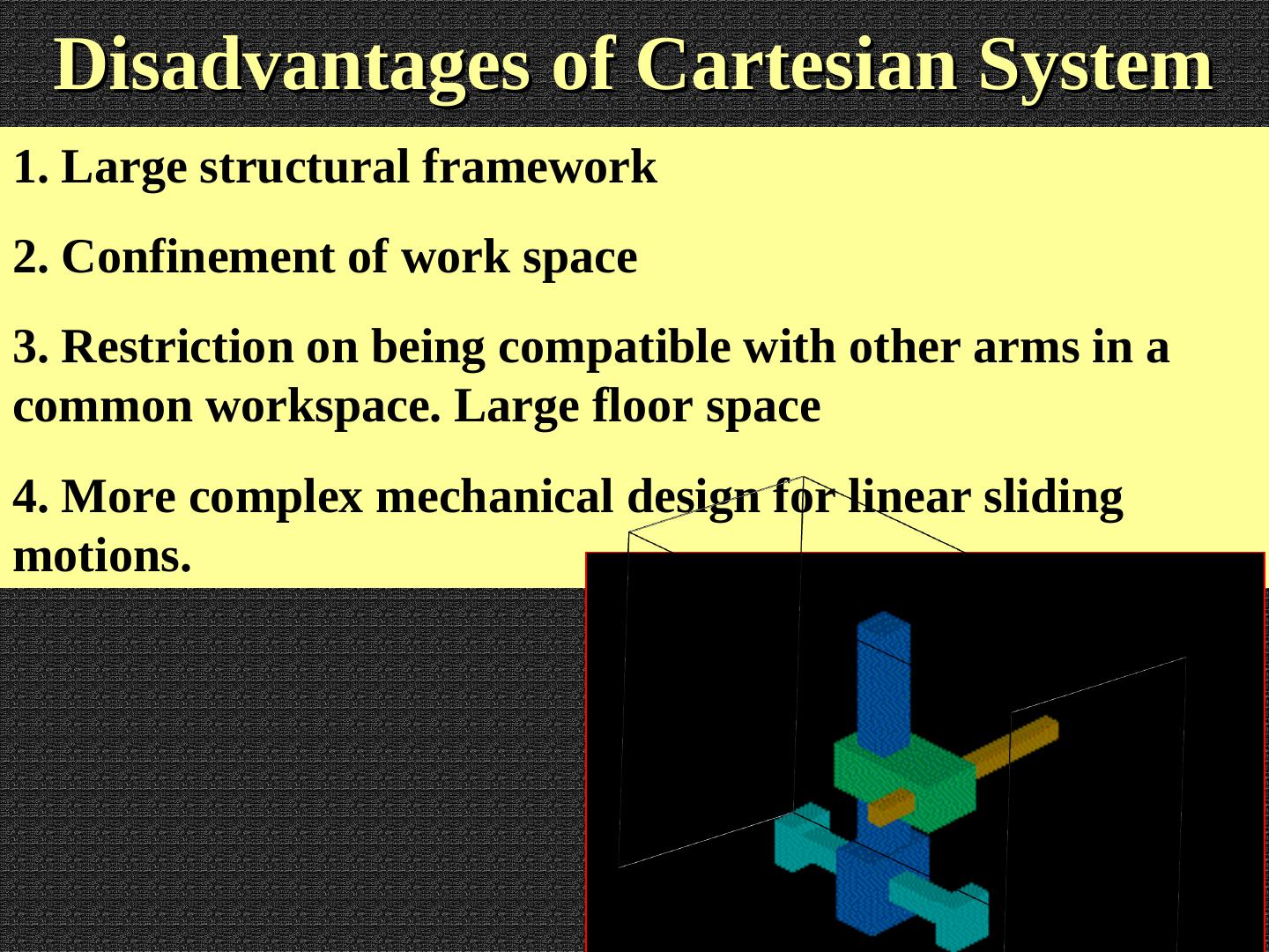
12 . Disadvantages of Cartesian System 1. Large structural framework 2. Confinement of work space 3. Restriction on being compatible with other arms in a common workspace. Large floor space 4. More complex mechanical design for linear sliding motions.
13 . Questions and Problems 1. Find a robot arm description in one of robot shops on internet. Describe it in the same way as the robot above. 2. For the above robot, plan how would you design it using components available in the lab. Create technical sketches and drawings. 3. Invent a robot arm with different arrangement of DOF than the Cartesian Coordinate system. 4. Assuming that you remember about basic high school mechanics like lever, gears and pulleys, perform power/torque/linkage calculations for the above robot. If you forgot, read the material from the forthcoming lectures.


