- 快召唤伙伴们来围观吧
- 微博 QQ QQ空间 贴吧
- 文档嵌入链接
- 复制
- 微信扫一扫分享
- 已成功复制到剪贴板
互补型MOS (CMOS)逻辑设计
展开查看详情
1 .NJIT ECE 271 Dr, Serhiy Levkov Topic 8 - 1 Topic 8 Complementary MOS (CMOS) Logic Design ECE 271 Electronic Circuits I
2 .NJIT ECE 271 Dr, Serhiy Levkov Topic 8 - 2 Chapter Goals Introduce CMOS logic concepts Explore the voltage transfer characteristics of CMOS inverters Learn to design basic and complex CMOS logic gates Discuss the static and dynamic power in CMOS logic Present expressions for dynamic performance of CMOS logic devices Present noise margins for CMOS logic Introduce design techniques for “cascade buffers”
3 .NJIT ECE 271 Dr, Serhiy Levkov Topic 8 - 3 CMOS Inverter Technology Complementary MOS, or CMOS, needs both PMOS and NMOS devices for the logic gates to be realized The concept of CMOS was introduced in 1963 by Wanlass and Sah. CMOS are more complicated in design and production, thus are more expensive to fabricate Have not been widely used until the 1980’s as NMOS microprocessors started to dissipating as much as 50 W and more and alternative design technique was needed CMOS dominate digital IC design today
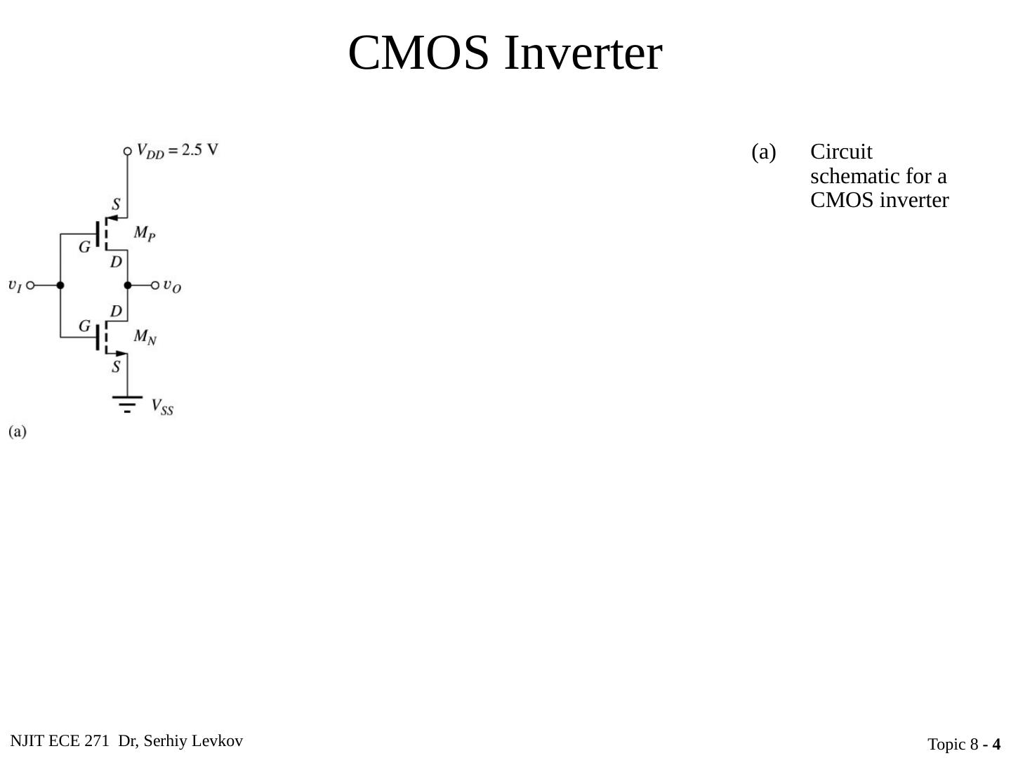
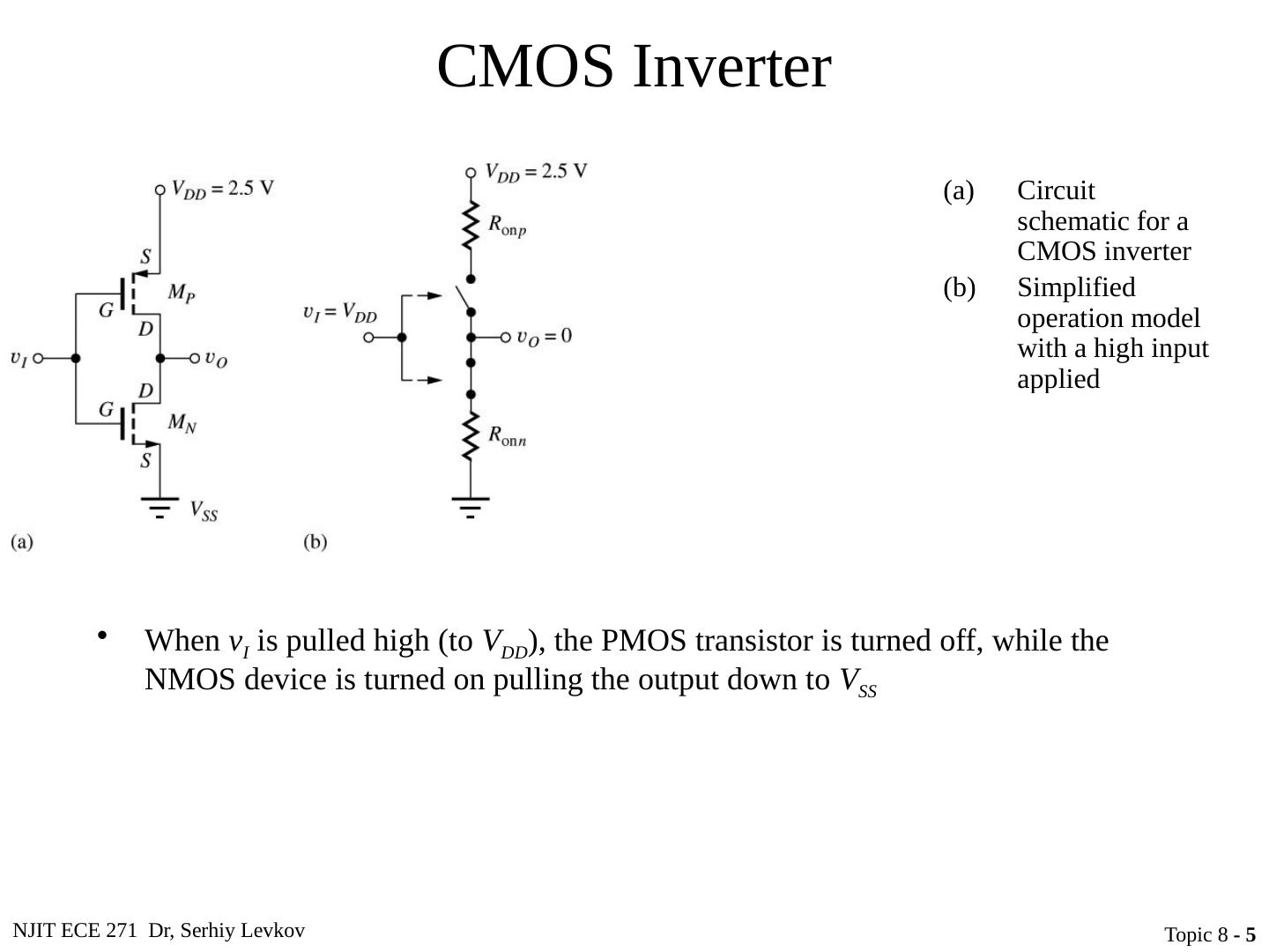
4 .NJIT ECE 271 Dr, Serhiy Levkov Topic 8 - 4 CMOS Inverter Circuit schematic for a CMOS inverter Simplified operation model with a high input applied Simplified operation model with a low input applied
5 .NJIT ECE 271 Dr, Serhiy Levkov Topic 8 - 5 CMOS Inverter Circuit schematic for a CMOS inverter Simplified operation model with a high input applied Simplified operation model with a low input applied When v I is pulled high (to V DD ), the PMOS transistor is turned off, while the NMOS device is turned on pulling the output down to V SS
6 .NJIT ECE 271 Dr, Serhiy Levkov Topic 8 - 6 CMOS Inverter Circuit schematic for a CMOS inverter Simplified operation model with a high input applied Simplified operation model with a low input applied When v I is pulled high (to V DD ), the PMOS transistor is turned off, while the NMOS device is turned on pulling the output down to V SS When v I is pulled low (to V SS ), the NMOS transistor is turned off, while the PMOS device is turned on pulling the output up to V DD
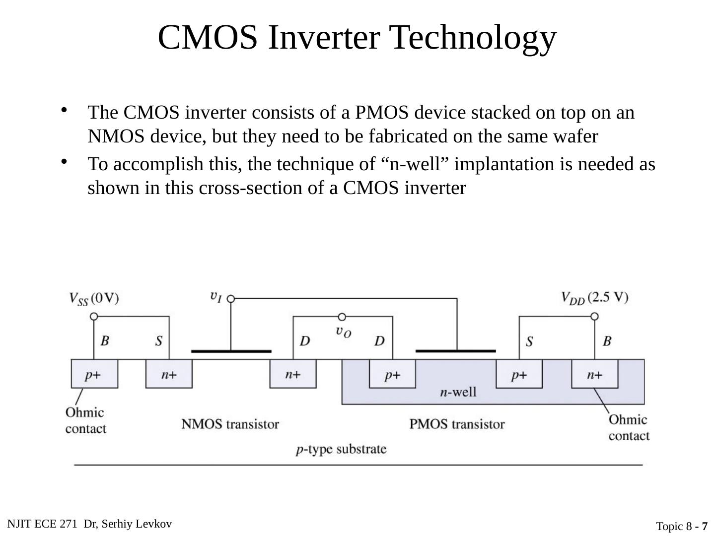
7 .NJIT ECE 271 Dr, Serhiy Levkov Topic 8 - 7 CMOS Inverter Technology The CMOS inverter consists of a PMOS device stacked on top on an NMOS device, but they need to be fabricated on the same wafer To accomplish this, the technique of “n-well” implantation is needed as shown in this cross-section of a CMOS inverter
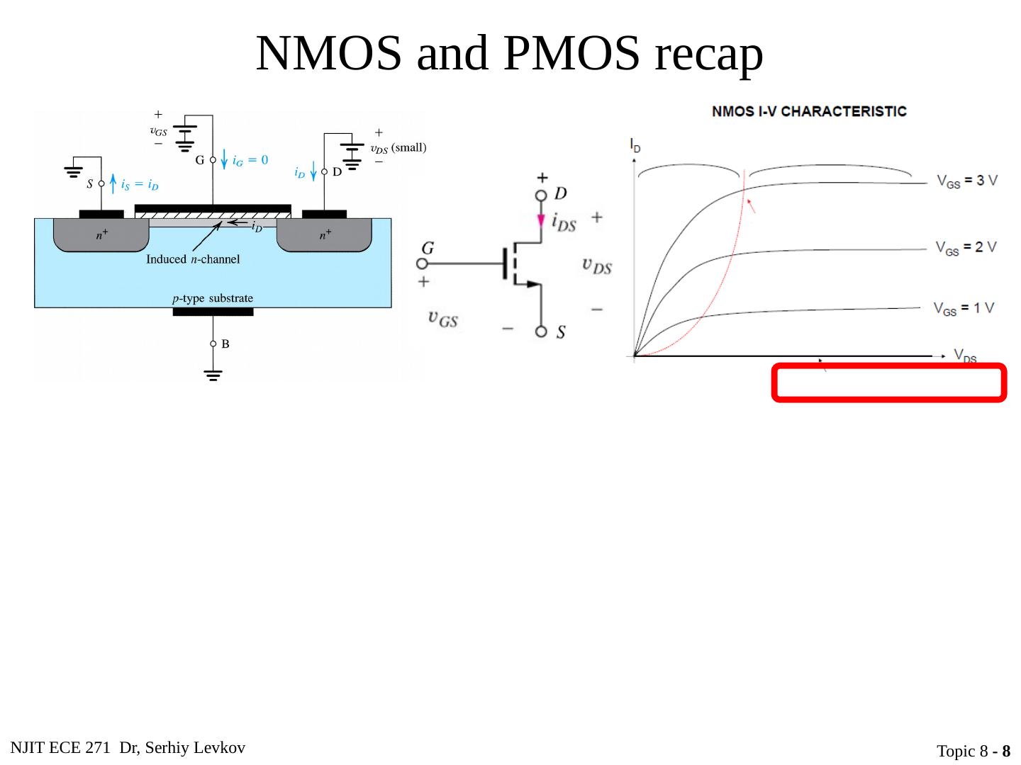
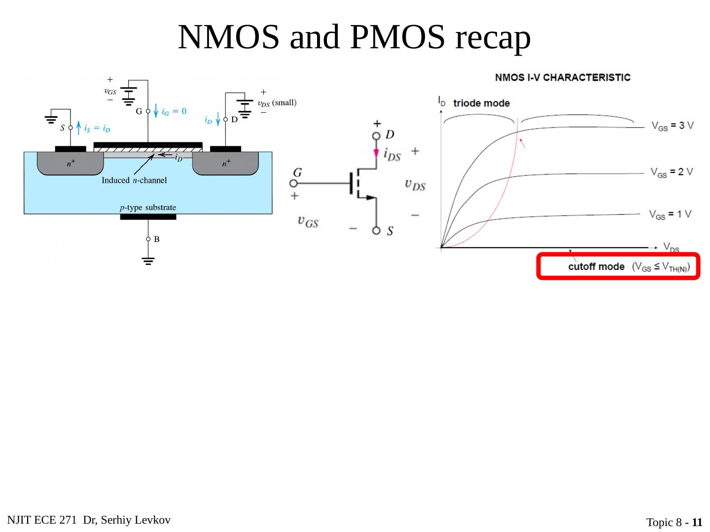
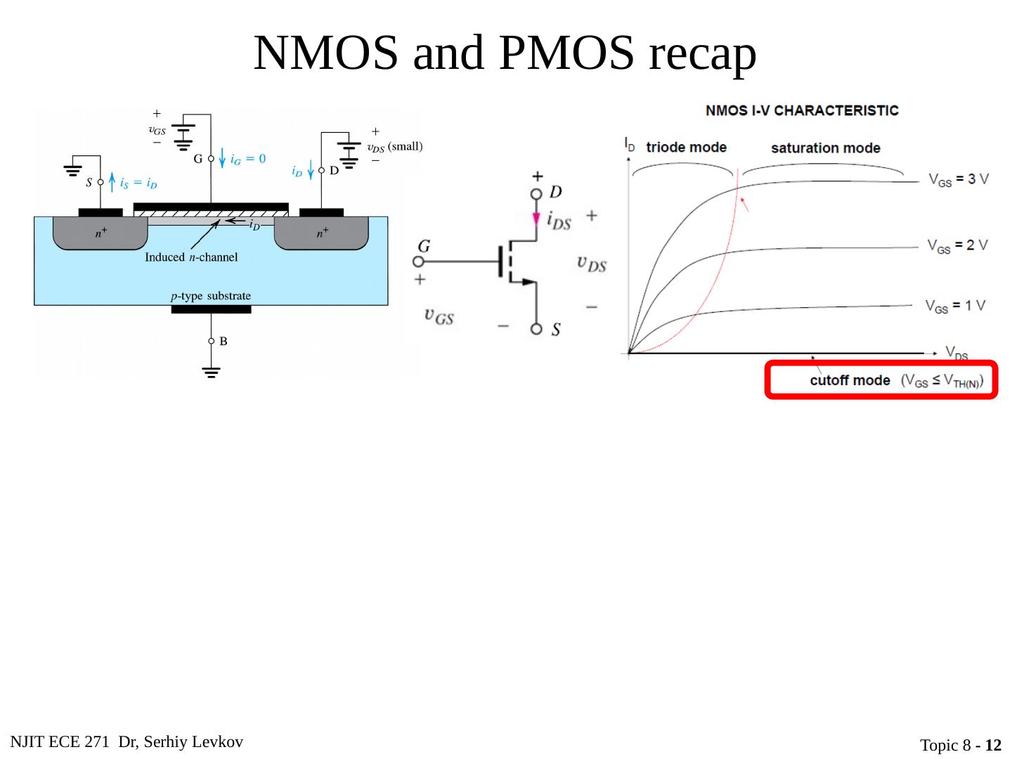
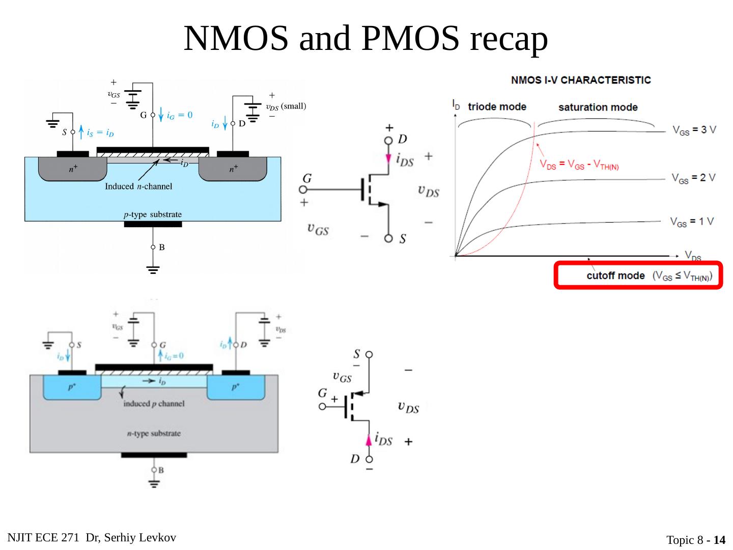
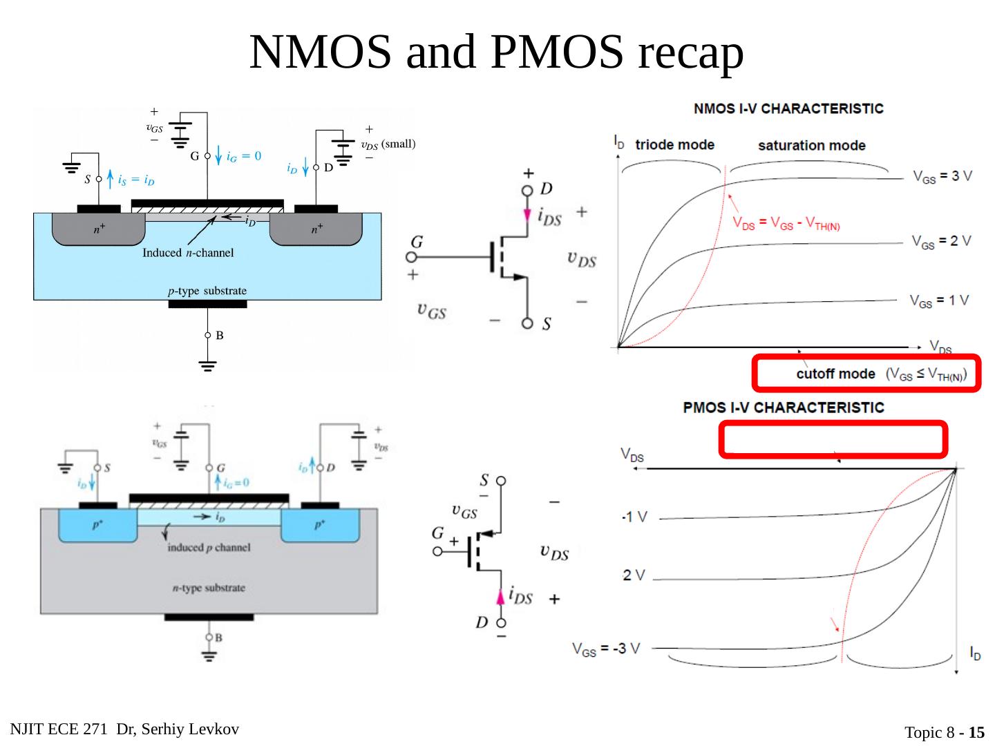
8 .NJIT ECE 271 Dr, Serhiy Levkov Topic 8 - 8 NMOS and PMOS recap
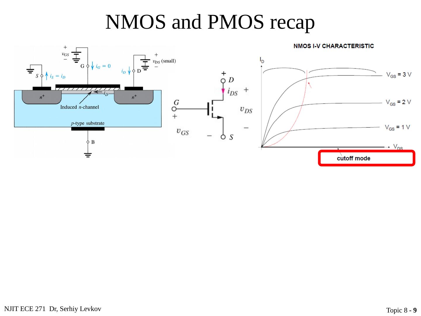
9 .NJIT ECE 271 Dr, Serhiy Levkov Topic 8 - 9 NMOS and PMOS recap
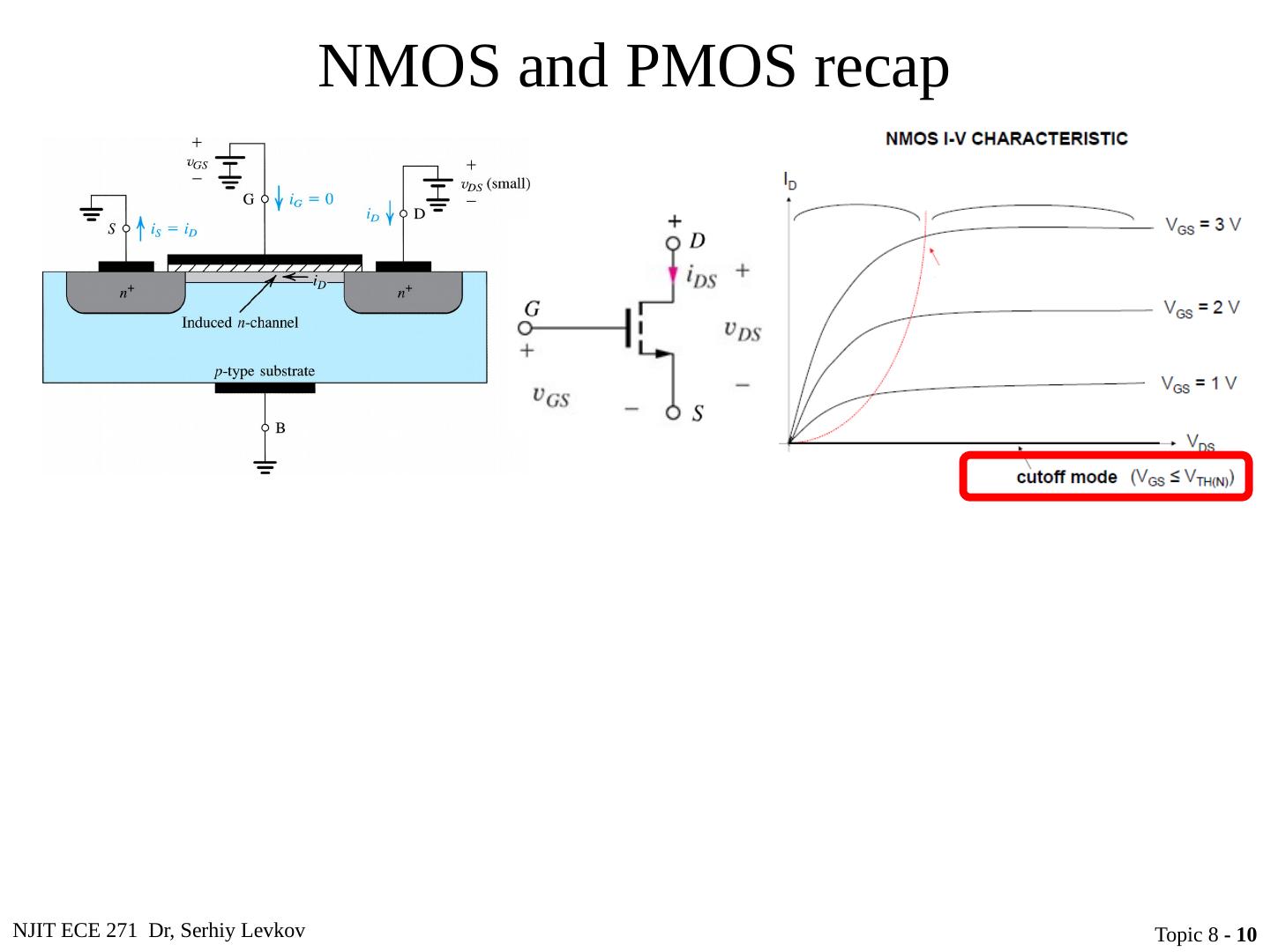
10 .NJIT ECE 271 Dr, Serhiy Levkov Topic 8 - 10 NMOS and PMOS recap
11 .NJIT ECE 271 Dr, Serhiy Levkov Topic 8 - 11 NMOS and PMOS recap
12 .NJIT ECE 271 Dr, Serhiy Levkov Topic 8 - 12 NMOS and PMOS recap
13 .NJIT ECE 271 Dr, Serhiy Levkov Topic 8 - 13 NMOS and PMOS recap
14 .NJIT ECE 271 Dr, Serhiy Levkov Topic 8 - 14 NMOS and PMOS recap
15 .NJIT ECE 271 Dr, Serhiy Levkov Topic 8 - 15 NMOS and PMOS recap
16 .NJIT ECE 271 Dr, Serhiy Levkov Topic 8 - 16 NMOS and PMOS recap
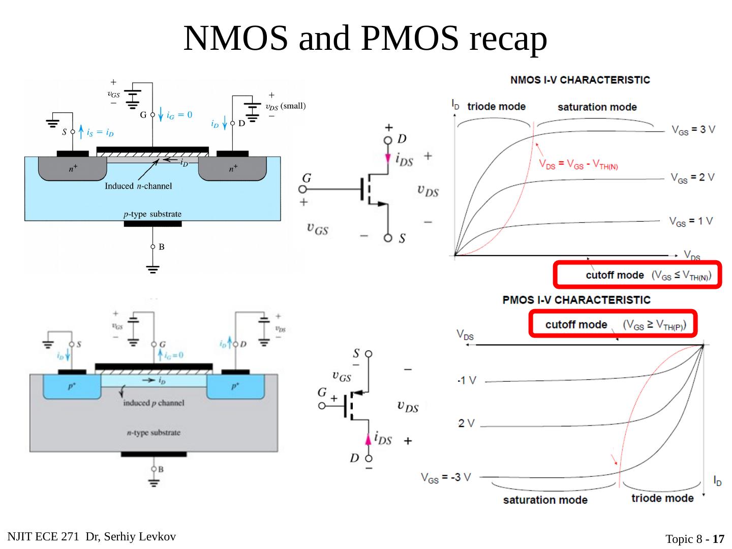
17 .NJIT ECE 271 Dr, Serhiy Levkov Topic 8 - 17 NMOS and PMOS recap
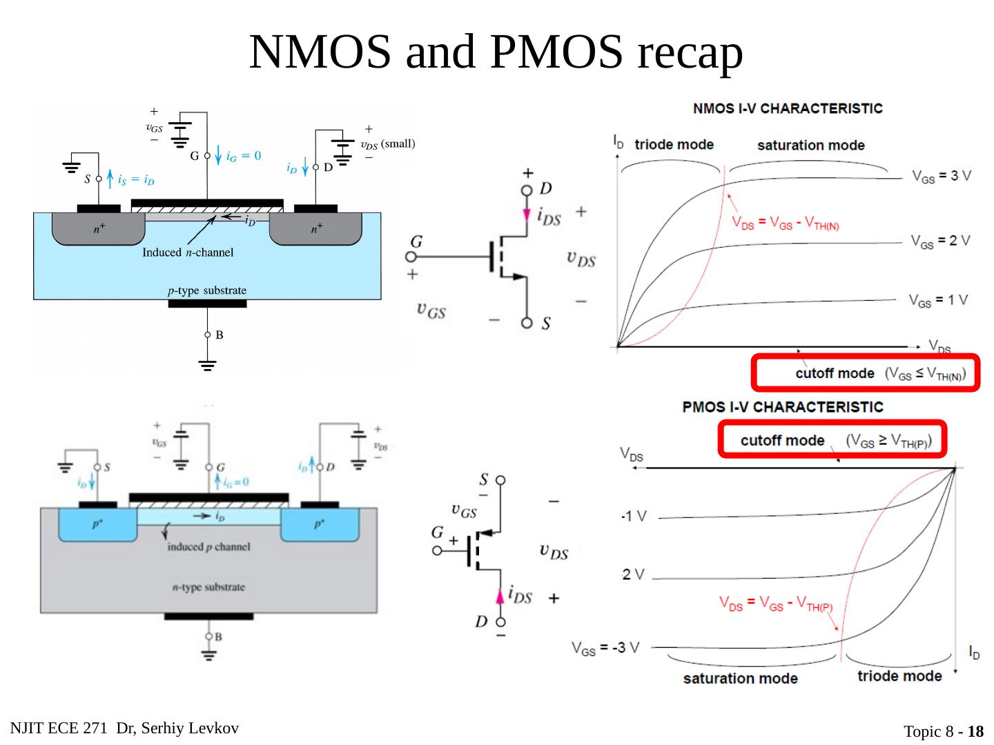
18 .NJIT ECE 271 Dr, Serhiy Levkov Topic 8 - 18 NMOS and PMOS recap
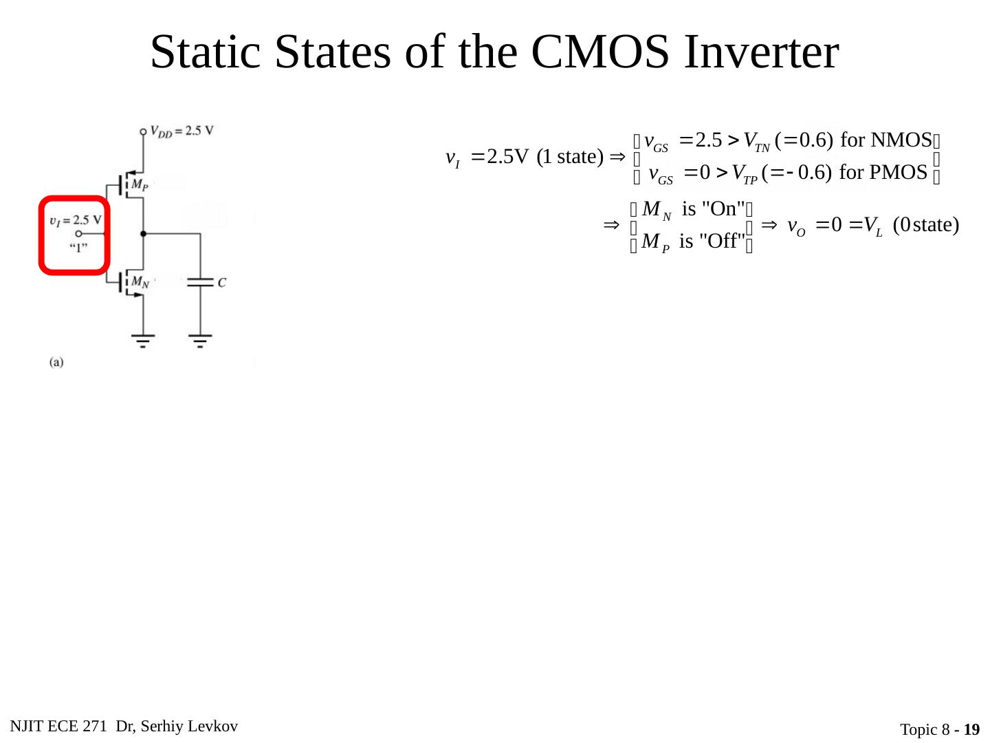
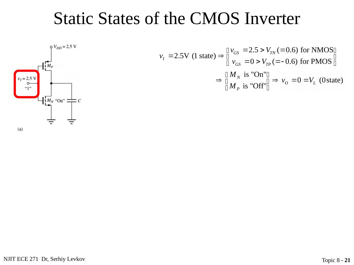
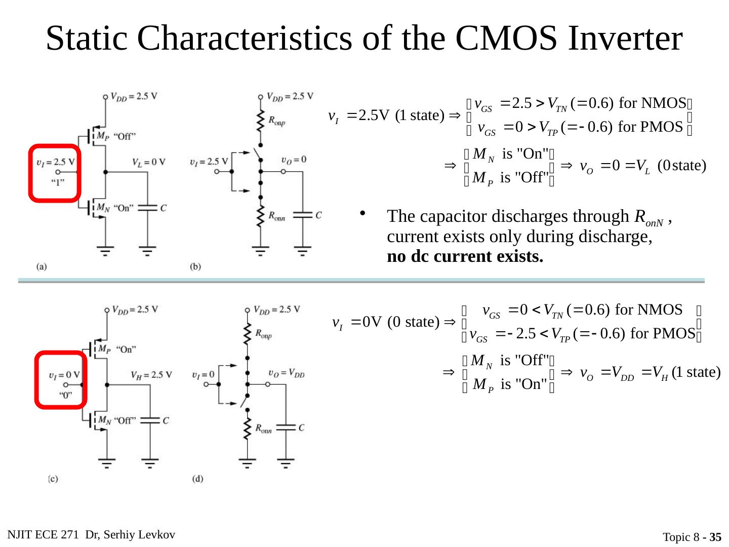
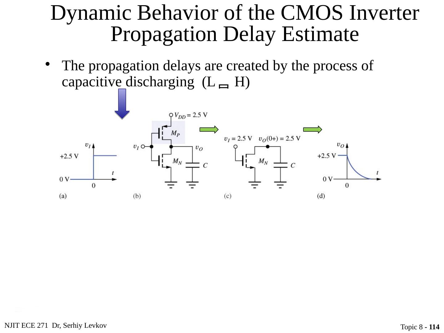
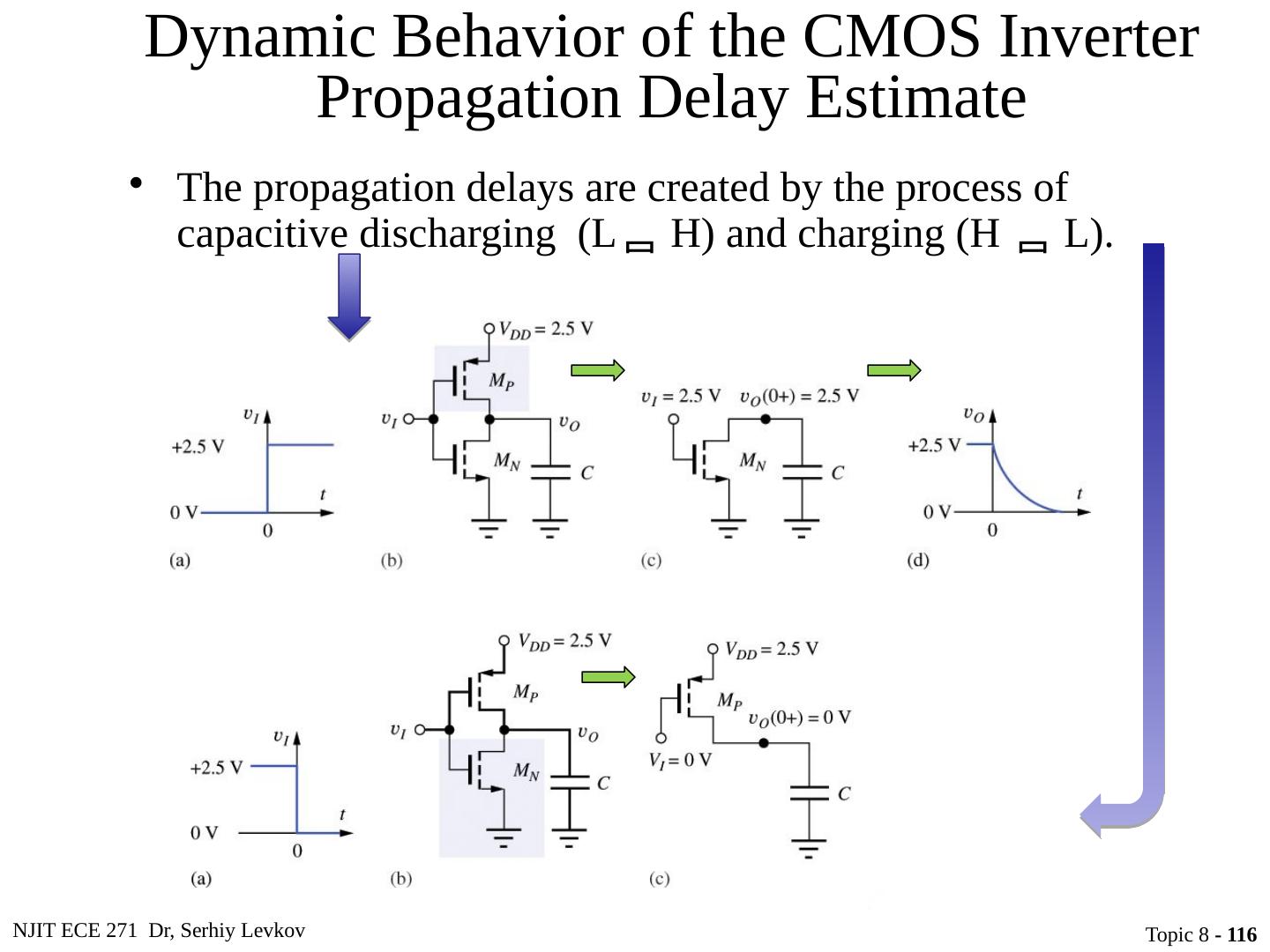
19 .NJIT ECE 271 Dr, Serhiy Levkov Topic 8 - 19 Static States of the CMOS Inverter The capacitor discharges through R onN , current exists only during discharge, no dc current exists.
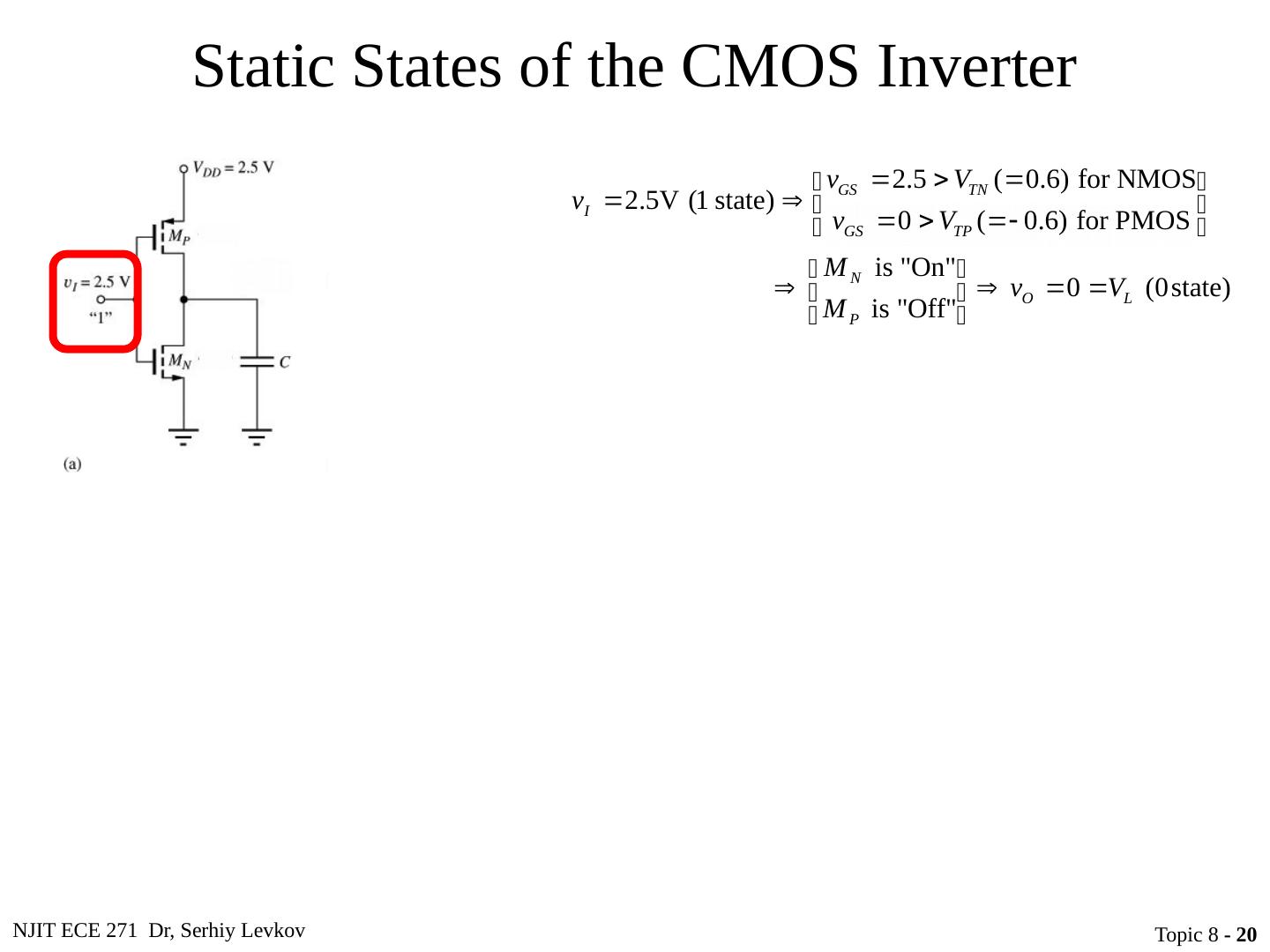
20 .NJIT ECE 271 Dr, Serhiy Levkov Topic 8 - 20 Static States of the CMOS Inverter The capacitor discharges through R onN , current exists only during discharge, no dc current exists.
21 .NJIT ECE 271 Dr, Serhiy Levkov Topic 8 - 21 Static States of the CMOS Inverter The capacitor discharges through R onN , current exists only during discharge, no dc current exists.
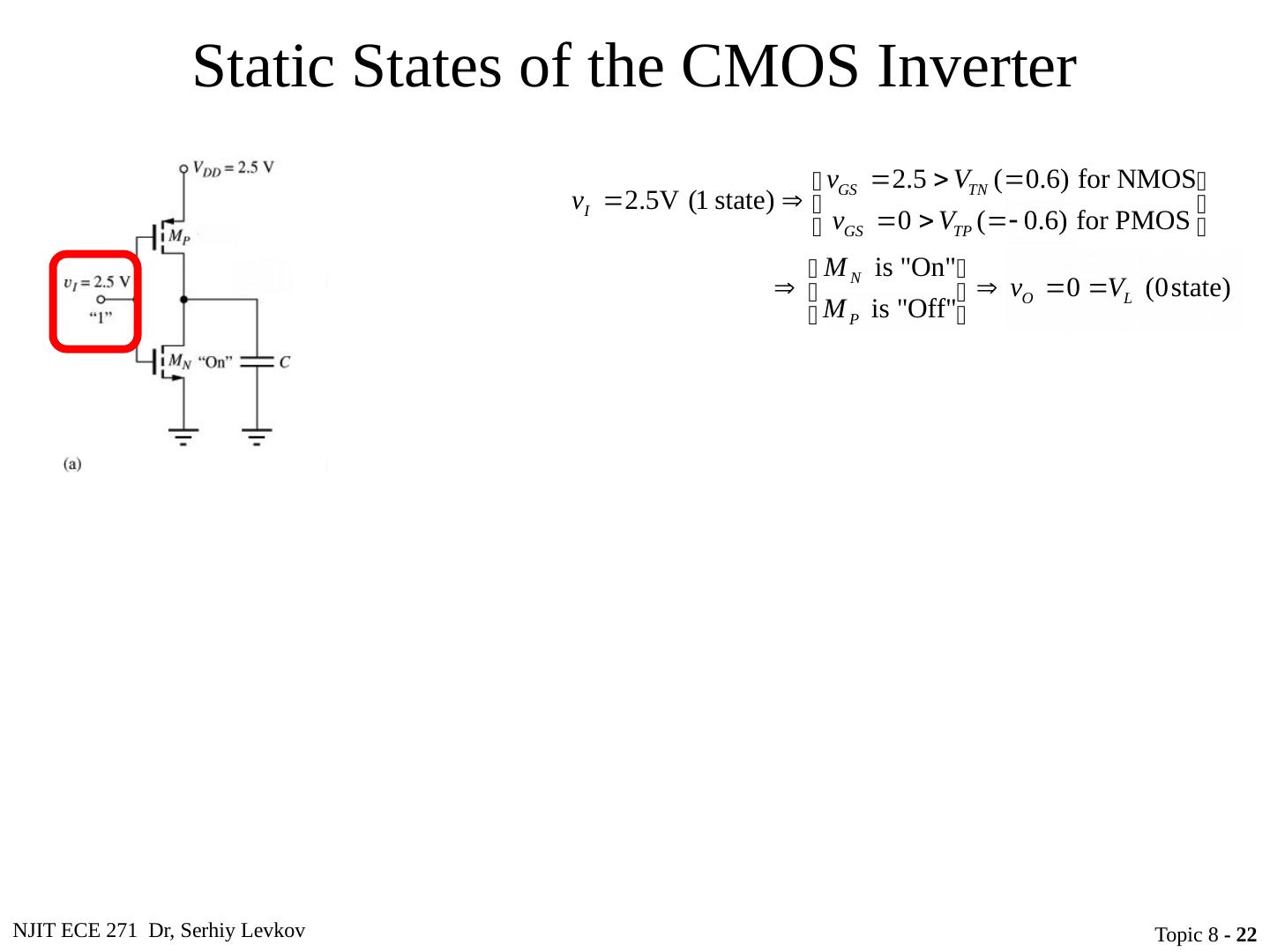
22 .NJIT ECE 271 Dr, Serhiy Levkov Topic 8 - 22 Static States of the CMOS Inverter The capacitor discharges through R onN , current exists only during discharge, no dc current exists.
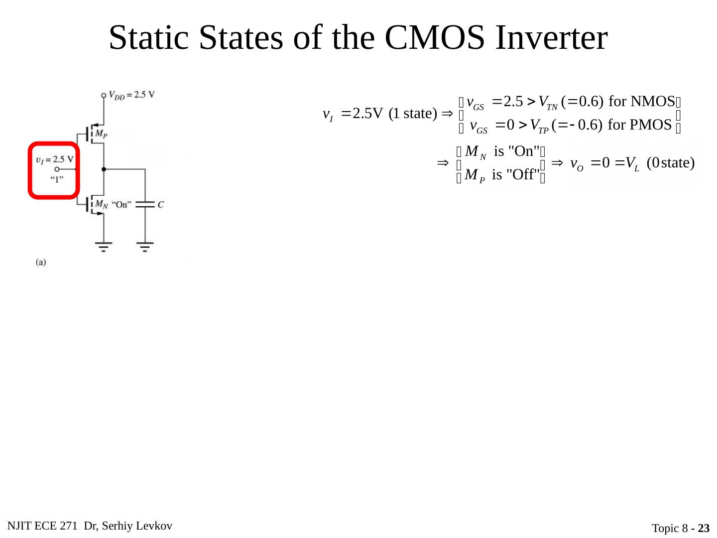
23 .NJIT ECE 271 Dr, Serhiy Levkov Topic 8 - 23 Static States of the CMOS Inverter The capacitor discharges through R onN , current exists only during discharge, no dc current exists.
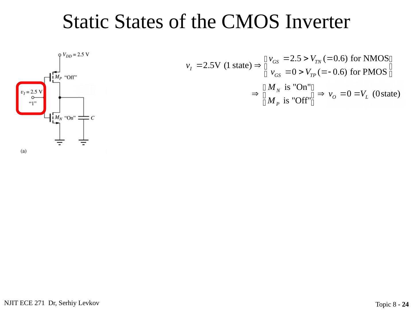
24 .NJIT ECE 271 Dr, Serhiy Levkov Topic 8 - 24 Static States of the CMOS Inverter The capacitor discharges through R onN , current exists only during discharge, no dc current exists.
25 .NJIT ECE 271 Dr, Serhiy Levkov Topic 8 - 25 Static States of the CMOS Inverter The capacitor discharges through R onN , current exists only during discharge, no dc current exists.
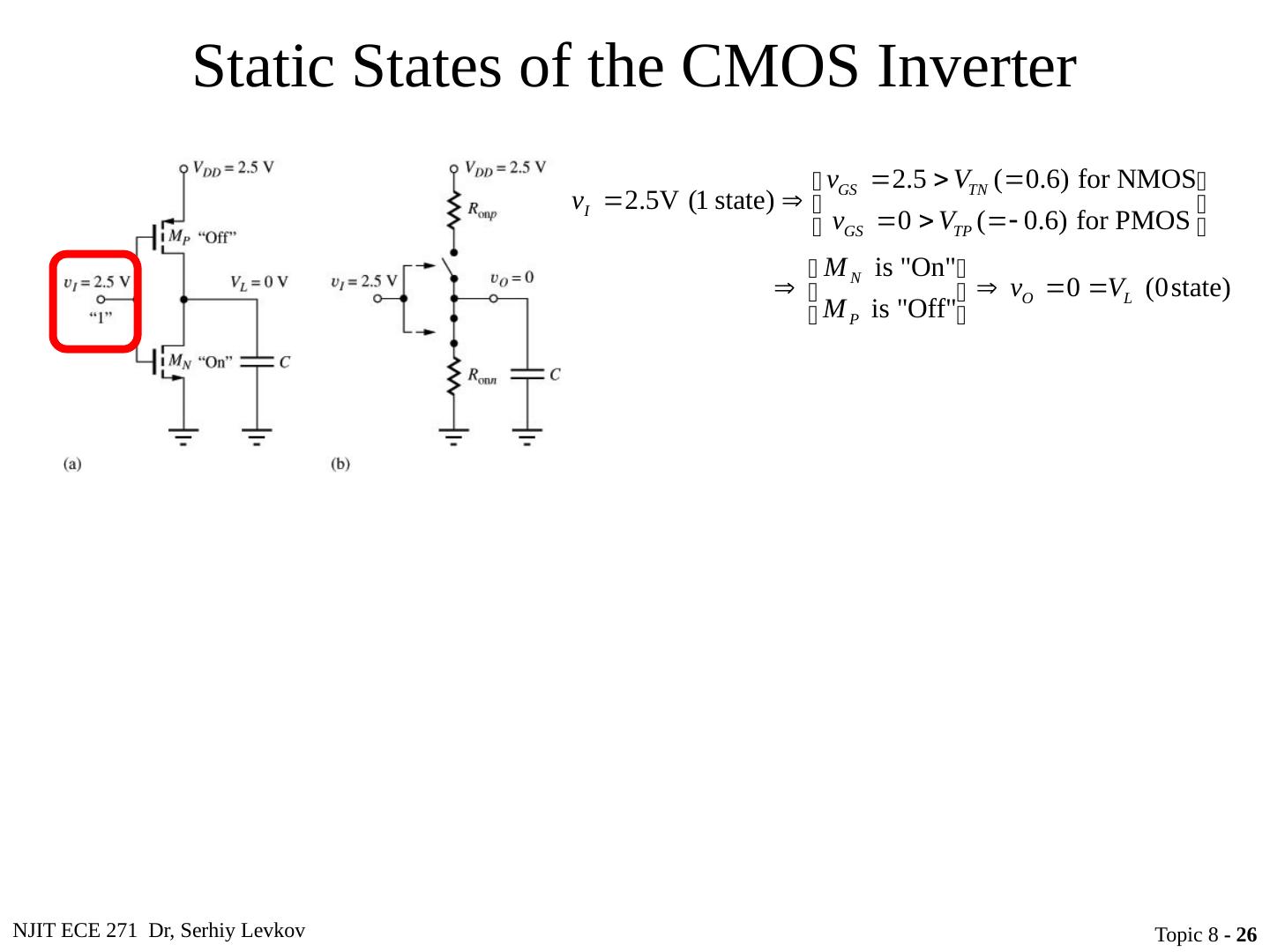
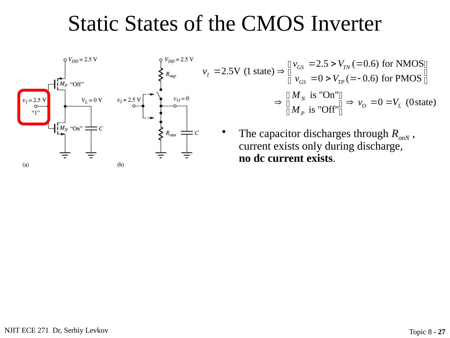
26 .NJIT ECE 271 Dr, Serhiy Levkov Topic 8 - 26 Static States of the CMOS Inverter The capacitor discharges through R onN , current exists only during discharge, no dc current exists.
27 .NJIT ECE 271 Dr, Serhiy Levkov Topic 8 - 27 Static States of the CMOS Inverter The capacitor discharges through R onN , current exists only during discharge, no dc current exists .
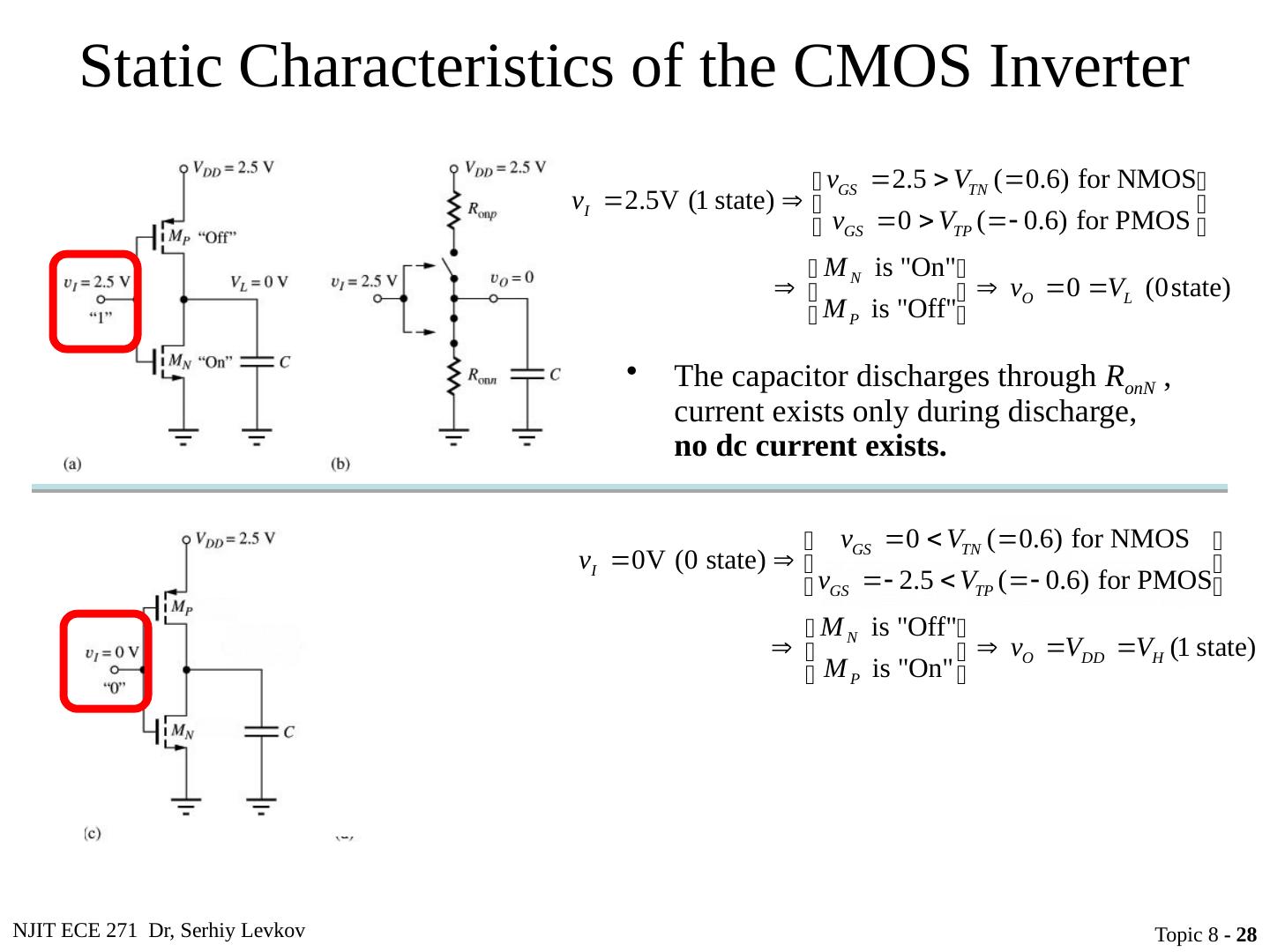
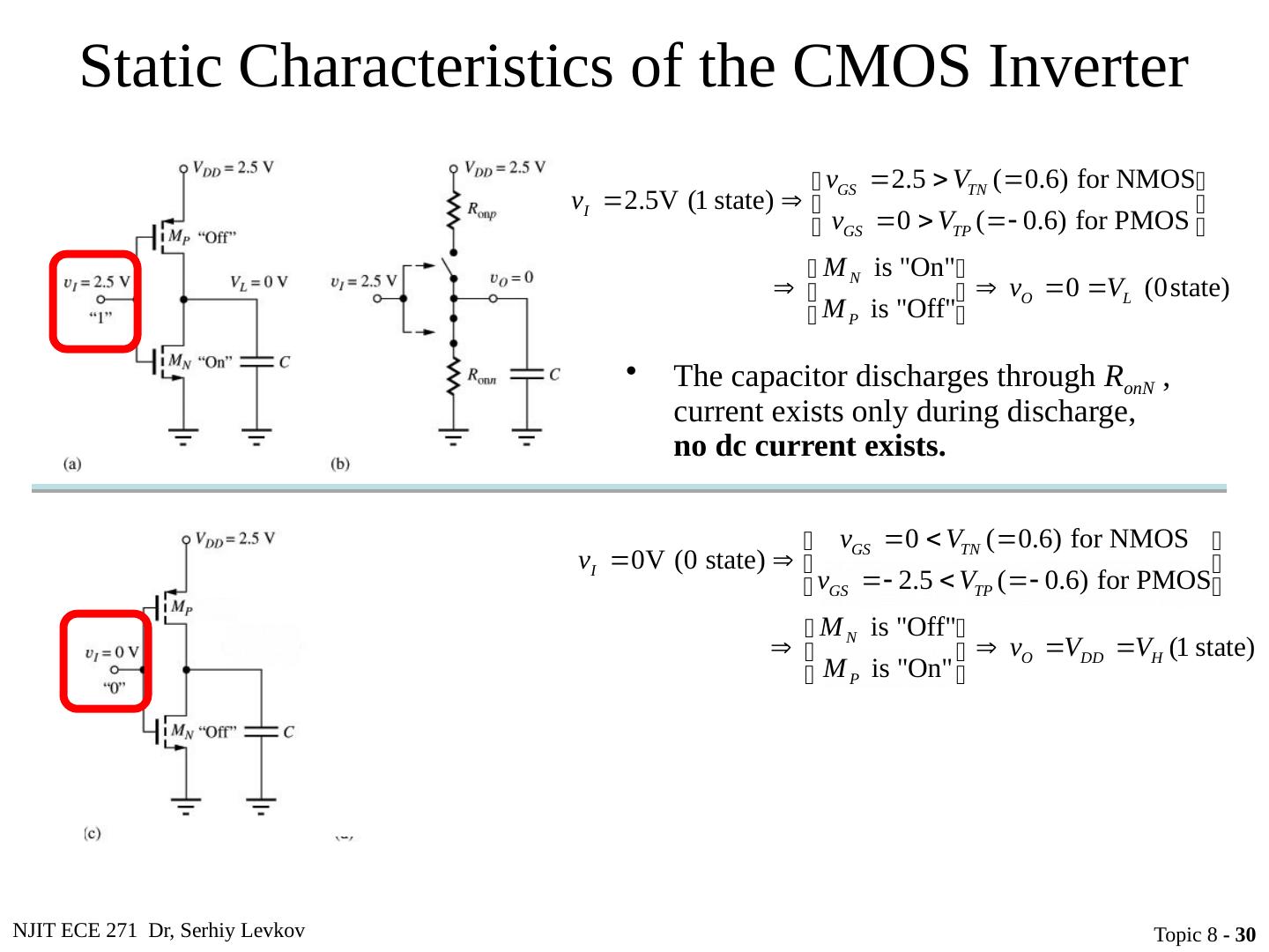
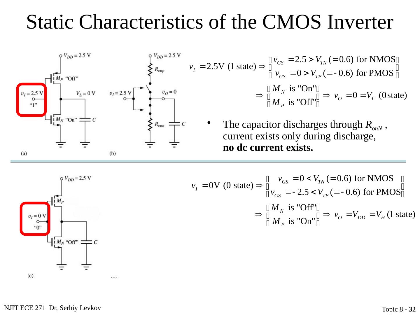
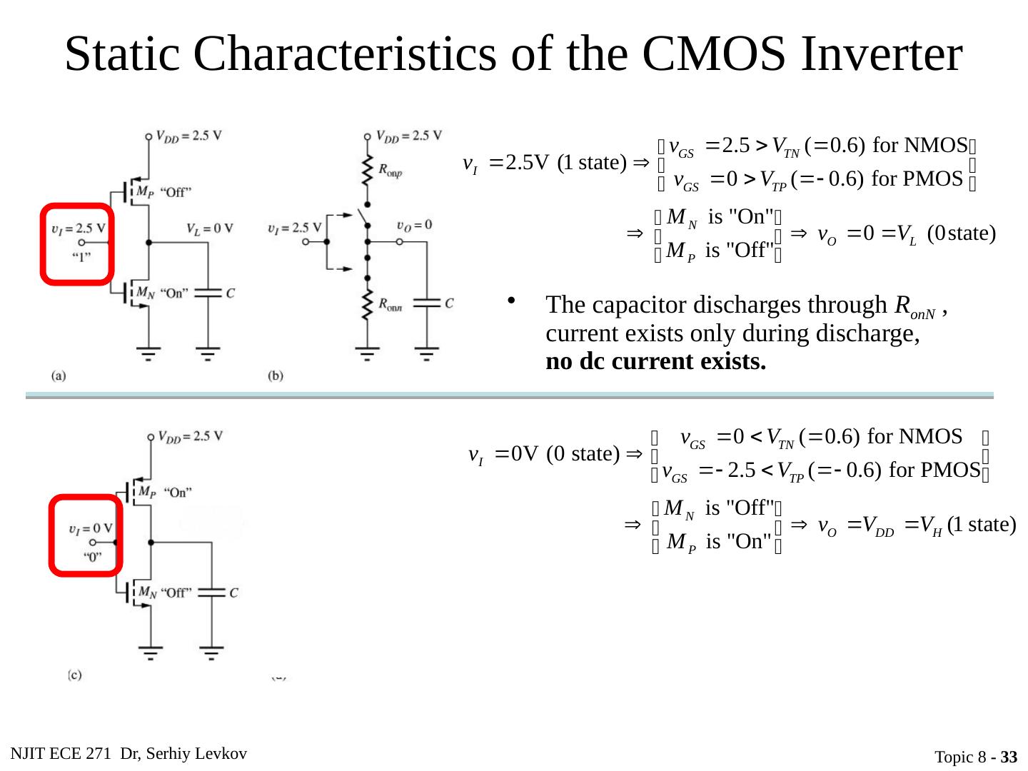
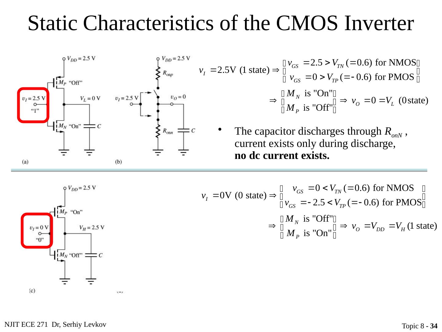
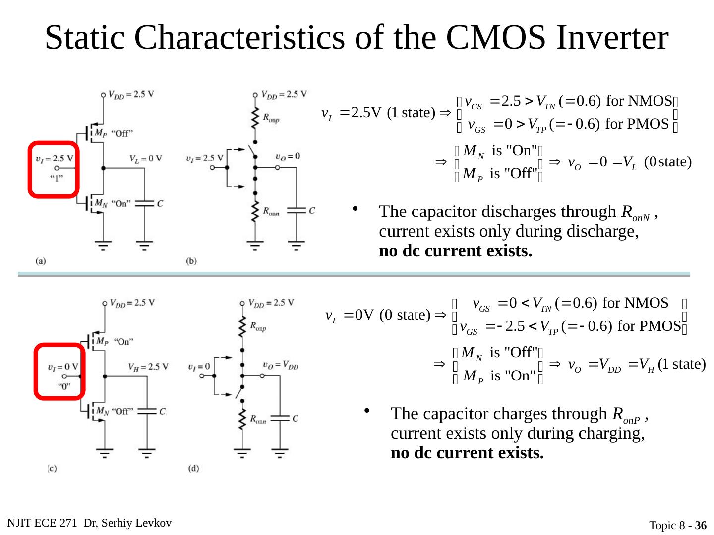
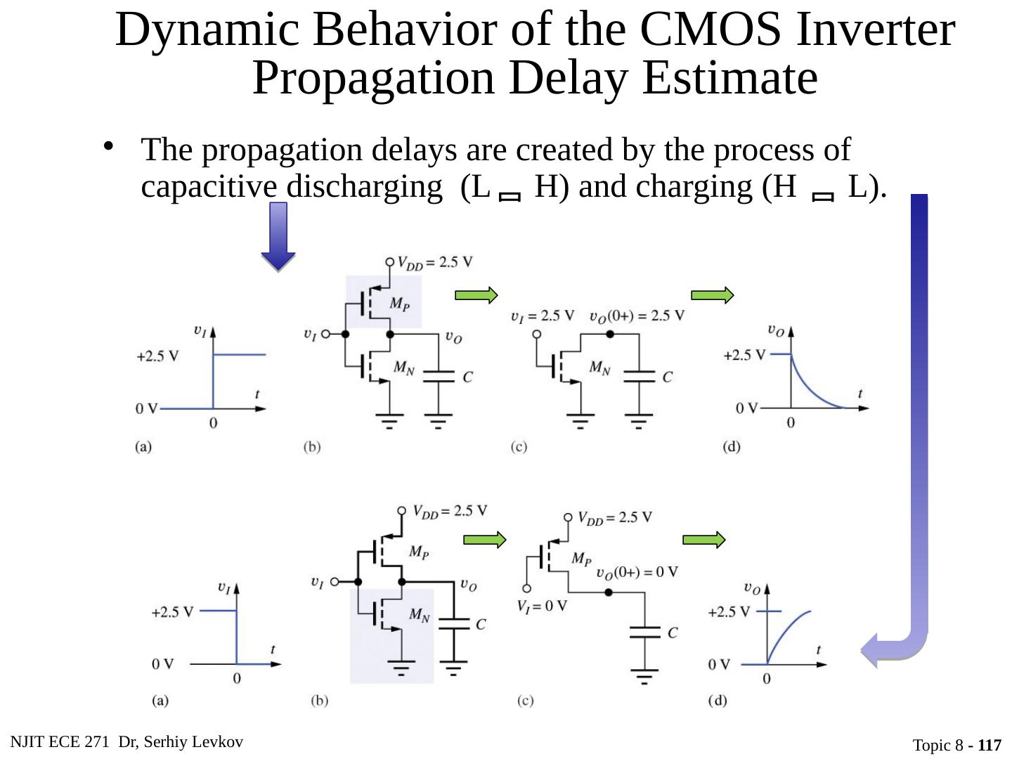
28 .NJIT ECE 271 Dr, Serhiy Levkov Topic 8 - 28 Static Characteristics of the CMOS Inverter The capacitor discharges through R onN , current exists only during discharge, no dc current exists. The capacitor charges through R onP , current exists only during charging, no dc current exists.
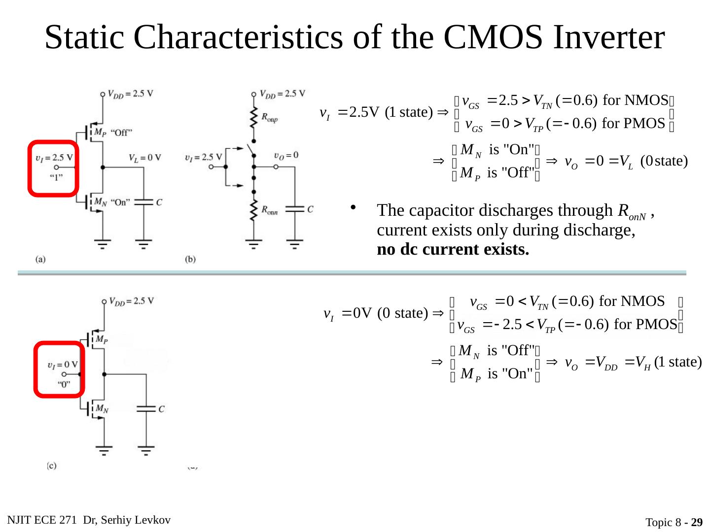
29 .NJIT ECE 271 Dr, Serhiy Levkov Topic 8 - 29 Static Characteristics of the CMOS Inverter The capacitor discharges through R onN , current exists only during discharge, no dc current exists. The capacitor charges through R onP , current exists only during charging, no dc current exists.


