- 快召唤伙伴们来围观吧
- 微博 QQ QQ空间 贴吧
- 文档嵌入链接
- 复制
- 微信扫一扫分享
- 已成功复制到剪贴板
运行时电路和系统优化
展开查看详情
1 .Optimizing Power @ Runtime Circuits and Systems
2 .Chapter Outline Motivation behind run-time optimization Dynamic voltage and frequency scaling Adaptive body biasing General self-adaptation Aggressive deployment Power domains and power management
3 .Why Run-Time Optimization for Power? Power dissipation strong function of activity In many applications, activity various strongly over time: Example 1: Operational load varies dramatically in general purpose computing. Some computations also requires faster response than others. Example 2: The amount of computation to be performed in many signal processing and communication functions (such as compression or filtering) is a function of the input data stream and its properties.. Optimum operation point in the performance-energy space hence varies over time Changes in manufacturing, environmental or aging conditions also lead to variable operation points Designs for a single fixed design point are sub-optimal
4 .Variable Workload in Media Processing Example: Video Compression [Courtesy: A. Chandrakasan ] Typical MPEG IDCT Histogram True also for voice processing, graphics, multimedia and communications
5 .Variable Workloads in General-Purpose Computing [Ref: A. Sinha , VLSI’01] Workload traces of three processor styles over 60 sec’s Laptop CPU usage chart File server Workstation Dialup server
6 .Adapting to Variable Workloads Goal: Position design in optimal operational point given required throughput Useful dynamic design parameters: V DD and V TH Changing transistor sizes dynamically non-trivial Variable supply voltage most effective for dynamic power reduction
7 .Adjusting Only the Clock Frequency Often used in portable processors Only reduces power – leaves energy/operation constant Does not save battery life Compute ASAP Delivered Throughput Clock Frequency Reduction Excess throughput Always high throughput Energy/operation remains unchanged while throughput scales down with f CLK f CLK Reduced time time [Ref: T. Burd , UCB’01]
8 .Dynamic Voltage Scaling (DVS) time Matches execution speed to requirements Minimizes average energy/operation Extends battery life up to one order of magnitude with the exact same hardware! Vary V DD and f CLK based on requested throughput Delivered Throughput [Ref: T. Burd , UCB’01]
9 .Flashback: V DD and Throughput 0.3 0.4 0.5 0.6 0.7 0.8 0.9 1 0.3 0.4 0.5 0.6 0.7 0.8 0.9 1 normalized performance f normalized supply v Nominal operation point With f and v the throughput and supply voltage normalized to the nominal values, and v t the ratio between threshold and nominal supply voltages. For a =2 and V DD >> V TH , f = v (long channel device)
10 .Dynamic Voltage Scaling (DVS) Reduces Dynamic Energy/Operation Superlinearly 0.2 0.3 0.4 0.5 0.6 0.7 0.8 0.9 1 0.1 0.2 0.3 0.4 0.5 0.6 0.7 0.8 0.9 1 normalized performance f normalized energy e Nominal operation point When performance is not needed, relax and save energy. ( a =1.3, V DDnom / V TH = 4)
11 .Dynamic Voltage Scaling (DVS) Even more impressive when considering power 0.2 0.3 0.4 0.5 0.6 0.7 0.8 0.9 1 0.1 0.2 0.3 0.4 0.5 0.6 0.7 0.8 0.9 1 normalized performance f normalized power p Nominal operation point Third order reduction in power when scaling supply voltage with workload (for a = 2 and V DD >> V TH ) ( a =1.3, V DDnom / V TH = 4) But … needs continuously variable supply voltage
12 .Using Discrete Voltage Levels DVS needs close integration with voltage regulation Continuously variable supply voltage not always available 0.2 0.3 0.4 0.5 0.6 0.7 0.8 0.9 1 0.1 0.2 0.3 0.4 0.5 0.6 0.7 0.8 0.9 1 normalized performance f normalized energy e Nominal operation point ( a =1.3, V DDnom / V TH = 4) V DDnom /2 Dithering supply voltage between discrete levels approximates continuous scaling Example: Operate 50% of time at V DDnom , and 50% at V DDnom /2 Reduces e to 0.625 for f = 0.74 Continuous DVS would yield e ≈ 0.5 [Ref: V. Gutnik , VLSI’96]
13 .Challenge: Estimating the Workload Adjusting supply voltage is not instantaneous and may take multiple clock cycles Efficiency of DVS strong function of accuracy in workload estimation Depending upon type of workload(s), their predictability and dynamism Stream-based computation General-purpose multi-processing
14 .Example 1: Stream-based Processing Examples: voice or multimedia processing FIFO REG Processor REG FIFO Control f clk V DD Stream in Stream out CLK FIFO measures workload Control dynamically adjusts V DD (and hence f clk ) [Ref: L. Nielsen, TVLSI’94]
15 .Stream-based Processing and Voltage Dithering MPEG-4 encoding Normalized power 0 0.2 0.4 0.6 0.8 1 2 3 8 # of frequency levels 1 Transition time between ƒ levels = 200 µ s Time n-th slice finished here Next milestone #n #n+1 Two hopping levels are sufficient. (also known as voltage hopping) [Ref: T. Sakurai, ISSCC’03 ]
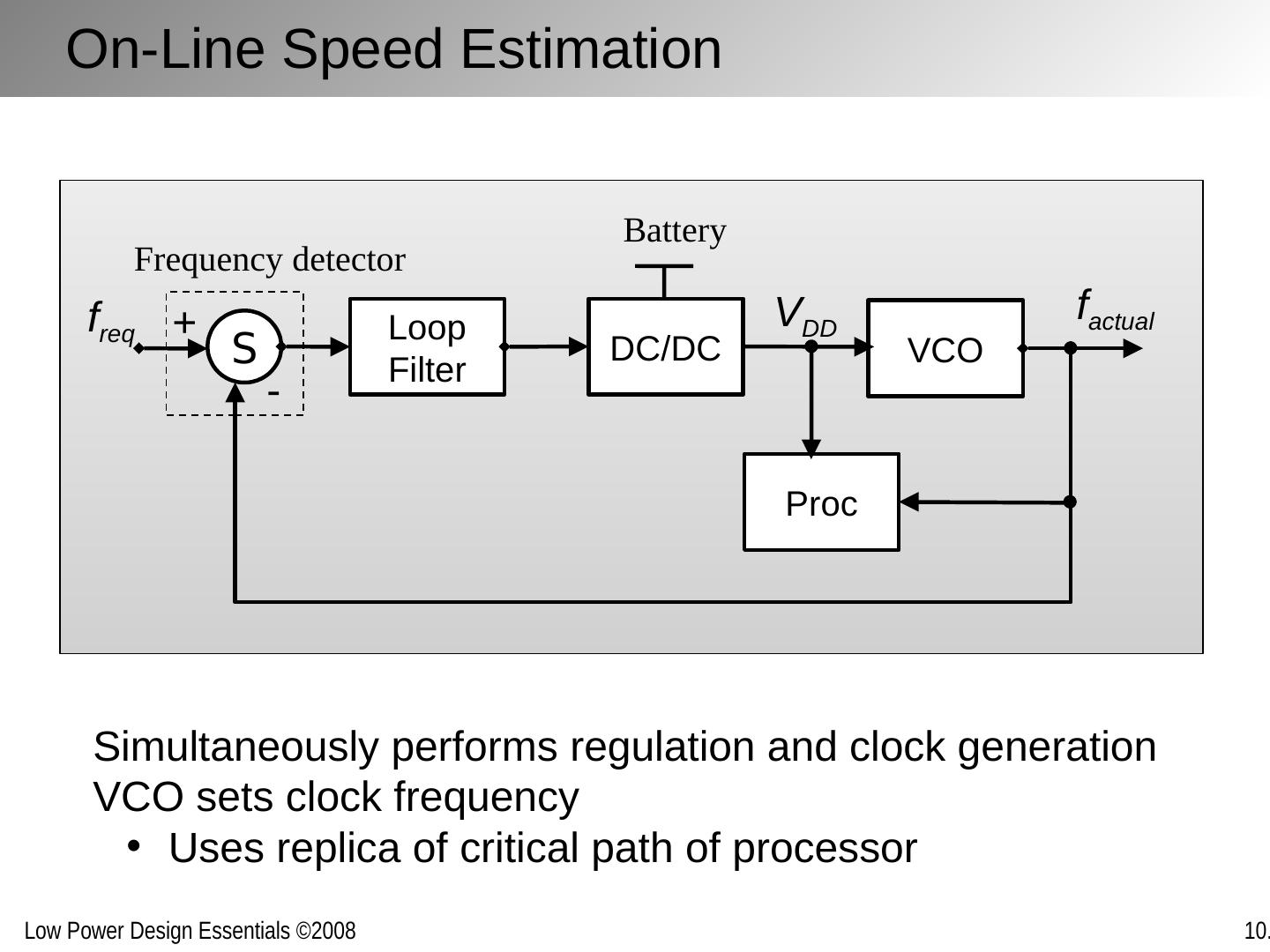
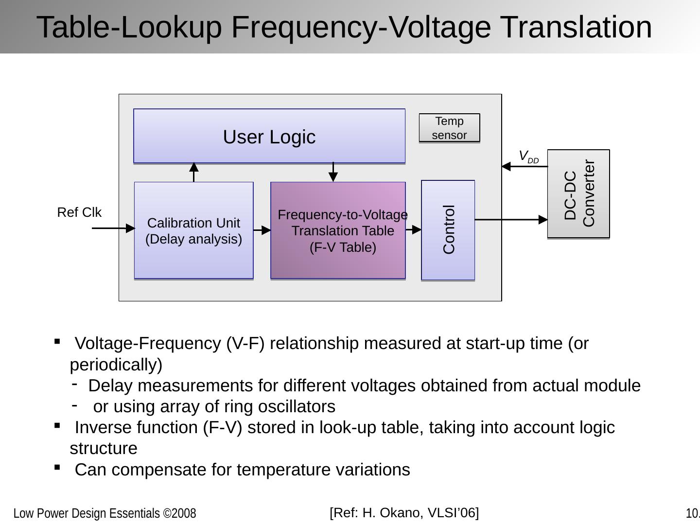
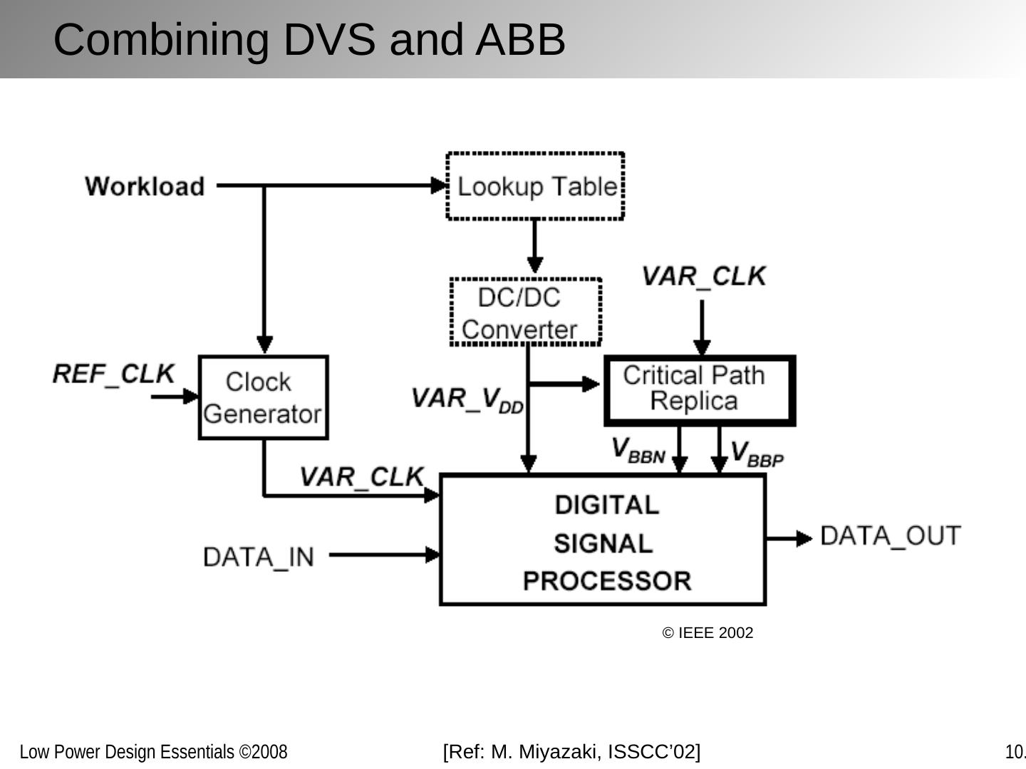
16 .Relating V DD and f clk Self-timed Avoids clock all-together Supply is set by close loop between V DD setting, processor speed, and FIFO occupation On-Line Speed Estimation Closed loop compares desired and actual frequency Needs “dummy” critical path to estimate actual delay Table-Look Up Stores relationship between f clk (processor speed) and V DD Obtained from simulations or calibration
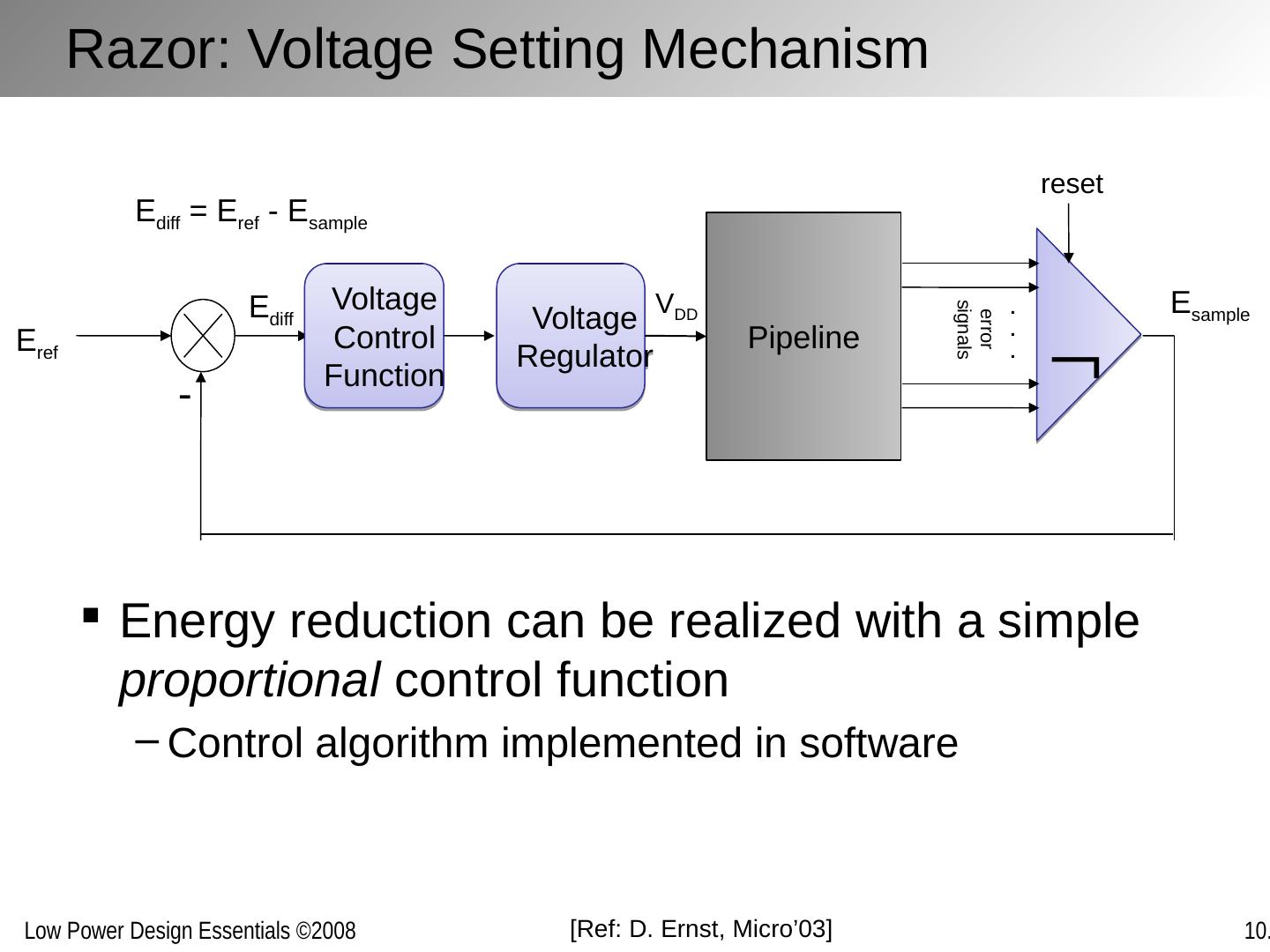
17 .On-Line Speed Estimation Simultaneously performs regulation and clock generation VCO sets clock frequency Uses replica of critical path of processor Frequency detector VCO DC/DC Loop Filter Proc S Battery + - f req f actual V DD
18 .Table-Lookup Frequency-Voltage Translation User Logic Calibration Unit (Delay analysis) Frequency-to-Voltage Translation Table (F-V Table) Control DC-DC Converter V DD Voltage-Frequency (V-F) relationship measured at start-up time (or periodically) Delay measurements for different voltages obtained from actual module or using array of ring oscillators Inverse function (F-V) stored in look-up table, taking into account logic structure Can compensate for temperature variations Temp sensor Ref Clk [Ref: H. Okano, VLSI’06]
19 .Example 2: General-Purpose Processor Controller Clock & V DD Required speed G.P. Processor Software/ OS Hardware Processor Speed (MPEG) F DESIRED (MHz) Time (sec) Applications supply completion deadlines. Voltage Scheduler (VS) predicts workload to estimate CPU cycles .
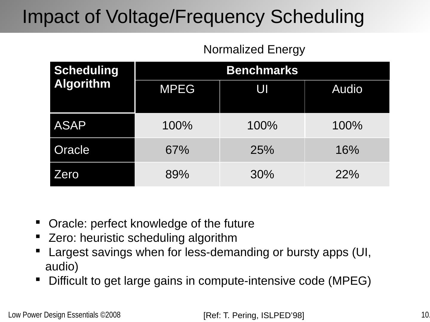
20 . Oracle: perfect knowledge of the future Zero: heuristic scheduling algorithm Largest savings when for less-demanding or bursty apps (UI, audio) Difficult to get large gains in compute-intensive code (MPEG) Normalized Energy Impact of Voltage/Frequency Scheduling [Ref: T. Pering , ISLPED’98] Scheduling Algorithm Benchmarks MPEG UI Audio ASAP 100% 100% 100% Oracle 67% 25% 16% Zero 89% 30% 22%
21 .1.0 3.5 1.0 3.5 V DD Max. Speed Idle Low Speed & Idle Increased speed for shorter process deadlines 200ms/div 200ms/div High-latency computation done @ low speed/energy Compute ASAP: With Voltage Scheduler: Impact of Voltage Scheduling Example: User interface processing (very bursty) V DD [Ref: T. Burd , JSSC’00]
22 .Converter Loop Sets V DD , f CLK RST Counter Latch Digital Loop Filter L C DD V DD P ENAB N ENAB S F ERR F MEAS f 1MHz 0110100 F DES + Register f CLK Ring Oscillator V BAT Processor I DD Operating system set F DES Ring oscillator delay-matched to CPU critical paths. Feedback loop sets V DD so that F ERR 0 . 7 Buck converter Set by O.S. [Ref: T. Burd , JSSC’00]
23 .100 80 60 40 20 0 0 1 2 3 4 5 6 Dhrystone 2.1 MIPS Energy ( mW /MIPS) 85 MIPS @ 5.6 mW /MIPS (3.8V) 6 MIPS @ 0.54 mW /MIPS (1.2V) If processor in low-performance mode most of the time: 85 MIPS processor @ 0.54 mW /MIPS x Dynamic V DD StaticV DD [Ref: T. Burd , JSSC’00] A High-Performance Processor at Low-Energy
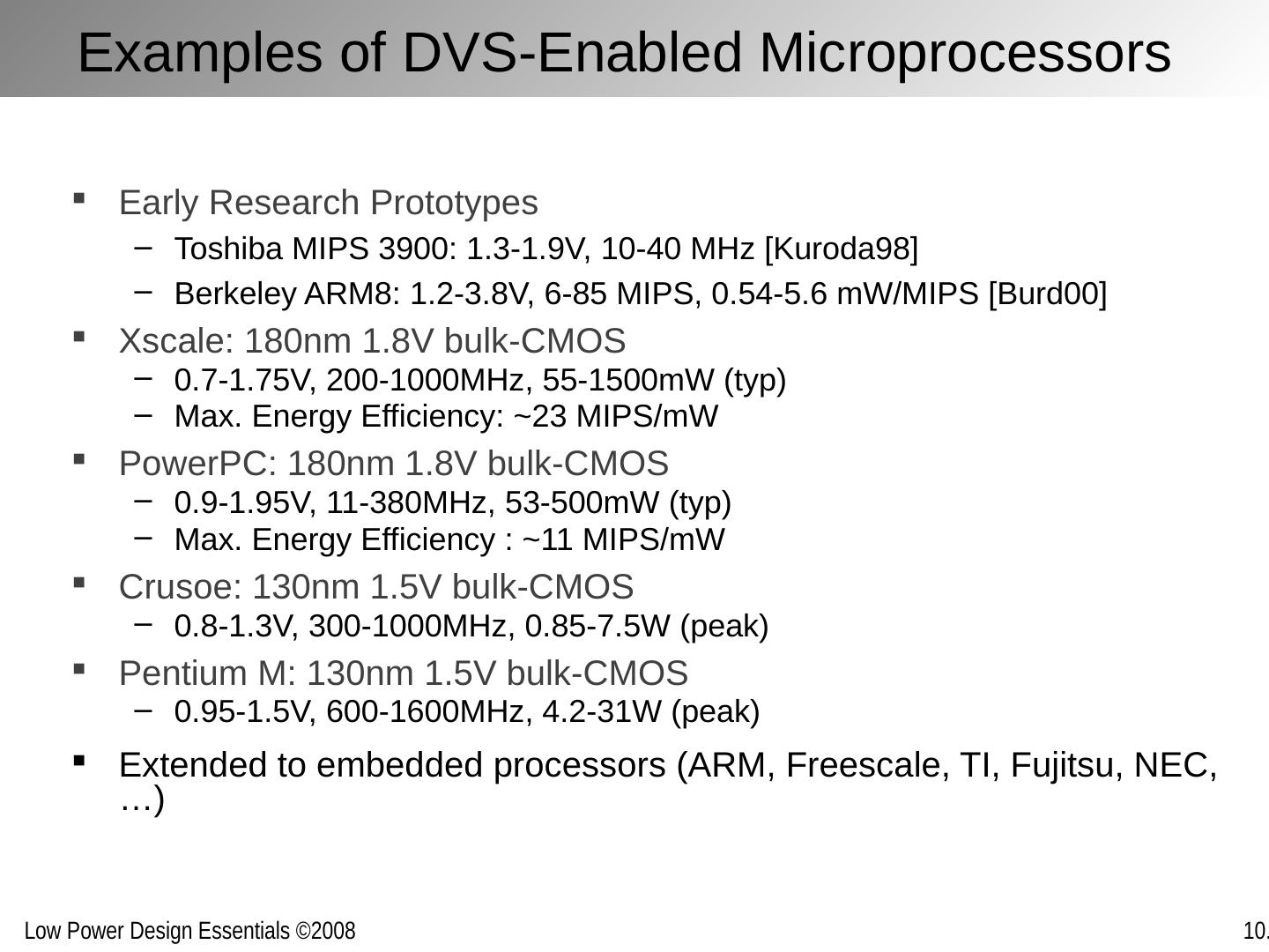
24 .Examples of DVS-Enabled Microprocessors Early Research Prototypes Toshiba MIPS 3900: 1.3-1.9V, 10-40 MHz [Kuroda98] Berkeley ARM8: 1.2-3.8V, 6-85 MIPS, 0.54-5.6 mW /MIPS [Burd00] Xscale : 180nm 1.8V bulk-CMOS 0.7-1.75V, 200-1000MHz, 55-1500mW ( typ ) Max. Energy Efficiency: ~23 MIPS/ mW PowerPC: 180nm 1.8V bulk-CMOS 0.9-1.95V, 11-380MHz, 53-500mW ( typ ) Max. Energy Efficiency : ~11 MIPS/ mW Crusoe: 130nm 1.5V bulk-CMOS 0.8-1.3V, 300-1000MHz, 0.85-7.5W (peak ) Pentium M: 130nm 1.5V bulk-CMOS 0.95-1.5V, 600-1600MHz, 4.2-31W (peak ) Extended to embedded processors (ARM, Freescale , TI, Fujitsu, NEC, …)
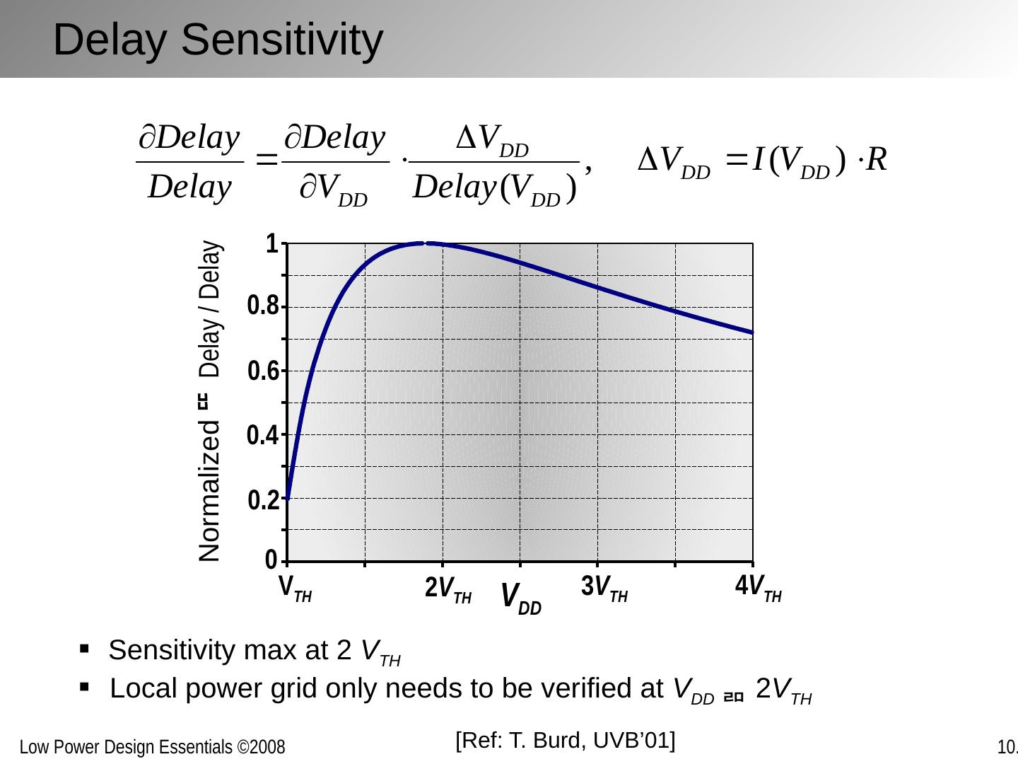
25 .DVS Challenge: Verification Functional verification Circuit design constraints Timing verification Circuit delay variation Power distribution integrity Noise margin reduction Delay sensitivities (local power grid) Need to verify at every voltage operation point?
26 .Logic needs to be functional under varying V DD Careful choice of logic styles is important (static versus dynamic, tri-state busses, memory cells, sense amplifiers Also: need to determine max | dV DD / dt | Design for Dynamically Varying V DD
27 . Static CMOS operates robustly with varying V DD Static CMOS Logic V DD In = 0 C L V out = V DD C L V DD V out R DS,PMOS
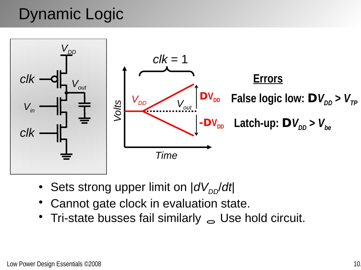
28 .V DD V out V in clk clk Volts Time V out V DD False logic low: D V DD > V TP Latch-up: D V DD > V be Errors Sets strong upper limit on | dV DD / dt | Cannot gate clock in evaluation state . Tri-state busses fail similarly Use hold circuit. clk = 1 D V DD -D V DD Dynamic Logic
29 .DVS System Transient Response 60 80 100 120 140 160 180 200 220 240 260 0 1 2 3 4 Time (ns) f CLK V DD Ring oscillator ( for | dV DD / dt | = 20 V/ m sec ) Output f CLK instantaneously adapts to new V DD . [Ref: T. Burd , JSSC’00] 0.6 m m CMOS


